Maytag MEDB765FW W10240504 - Page 8
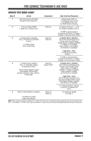
SERVICE TEST MODE CHART continued
 |
View all Maytag MEDB765FW manuals
Add to My Manuals
Save this manual to your list of manuals |
Page 8 highlights
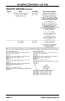
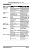
FOR SERVICE TECHNICIAN'S USE ONLY SERVICE TEST MODE CHART (continued) Step # Action Component User Interface Response 6 Load Mass for Airflow completes. Motor On/Off The update for Status_Airflow Heater On/Off is published to the UI. If electric (Fuel = Electric): The UI will report findings per the "Electric Dryer Results Display" section where L2 Voltage is available, L1 Voltage is available, Heater Voltage is available, and Airflow is available. If gas (Fuel = Gas): The UI will report findings per the "Gas Dryer Results Display" section where Heater Voltage is available and Airflow is available. If a "Detecting Airflow" LED is present, it is turned off. If a "Good Airflow" LED is present, it also displays when the Status_Airflow = 0. If a "Check Vent" LED is present, it also displays when the Status_Airflow = 2. 7 Service Loads Motor Off Test complete. Heater Off UI & Status LEDs continue to display as in step 6. The UI waits for "ServiceTimeout" or pressing of POWER to go to Standby mode. NOTE: Electric dryer performance is optimized for 2-phase, 240 VAC service. If complaint is made regarding electric dryer performance and the L1 to L2 voltage is ~208 VAC, dryer may be connected to a 3-phase service with reduced wattage that will decrease dryer performance. Electric Dryer Results Display The frame rate will be 0.5 seconds per frame. This sequence will repeat. The text will be right aligned. Frame 1: L2 Frame 2: When the voltage is available to the UI, it will display it without illuminating the colon (range 0 to 200). Frame 3: L1 Frame 4: When the voltage is available to the UI, it will display it without illuminating the colon (range 0 to 200). Frame 5: Htr Frame 6: When the voltage is available to the UI, it will display it without illuminating the colon (range 0 to 200). Frame 7: Air Frame 8: See "Airflow Display Section". When the voltage or airflow is not yet available to the UI, the display will show "---". Gas Dryer Results Display The frame rate will be 0.5 seconds per frame. This sequence will repeat. The text will be right aligned. Frame 1: Htr Frame 2: When the voltage is available to the UI, it will display it without illuminating the colon (range 0 to 200). Frame 3: Air Frame 4: See "Airflow Display Section". When the voltage or airflow is not yet available to the UI, the display will show "---". Airflow Display Value 0 1 2 3 (Default) Setting Airflow not bad Cannot detect Airflow bad; check vent Detecting If the result is not yet available, it will be displayed as "---". Status_Airflow = 0 will be displayed as: "0:00". Status_Airflow = 1 will be displayed as: "0:01". Status_Airflow = 2 will be displayed as: "0:02". Status_Airflow = 3 will be displayed as: "0:03". PAGE 8 DO NOT REMOVE OR DESTROY
-
 1
1 -
2
-
 3
3 -
 4
4 -
 5
5 -
 6
6 -
 7
7 -
 8
8 -
 9
9 -
 10
10 -
 11
11 -
 12
12 -
 13
13 -
14
-
15
-
16
-
17
-
18
-
19
-
20
-
21
-
22
-
23
-
24
-
25
-
26
-
27
-
28
-
29
-
30
-
31
-
32
-
33
-
34
-
35
-
36
-
37
-
38
-
39
-
40
-
41
-
42
-
43
-
44
-
45
-
46
-
47
-
48
-
49
-
50
-
51
-
52
-
53
-
54
-
55
-
56
 |
 |