Maytag MEDB765FW W10240504 - Page 21
TEST #5a: Adjusting Customer, Focused Dryness Level, TEST #6: Buttons and Indicators
 |
View all Maytag MEDB765FW manuals
Add to My Manuals
Save this manual to your list of manuals |
Page 21 highlights
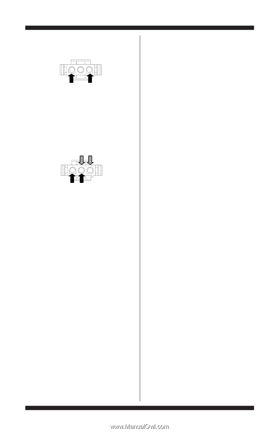
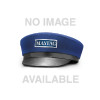
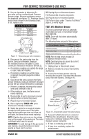
FOR SERVICE TECHNICIAN'S USE ONLY 5. Measure the resistance across the outermost contacts of the connector that includes the two MOVs. If a small resistance is measured, clean the two metal moisture strips inside the drum. If a small resistance is measured after cleaning, replace the sensor harness. If a small resistance is not measured, go to step 6. 6. Measure the resistance across each of the outermost contacts and the center terminal (ground connection). The dryer will beep and the current dryness setting will be displayed on the 7-segment display. The factory default value is "2". 2. Pressing the dryness or dry level button cycles the dryness setting between 0, 1, 2, 3, and 4, starting at the current setting. The new setting is displayed in the 7-segment display. 3. With the display showing the desired dryness setting, press the START button to save the drying mode and exit to standby mode (the START button in this mode does not start a drying cycle). The result will be stored in EEPROM of the ACU and will be retained after a power loss. NOTE: If there is no user activity for 20 seconds, or a button other than START, DRYNESS, or DRY LEVEL is pressed, the dryness setting is reverted back to its previous setting. 4. Press the POWER button at any time to cancel changes and exit from this mode. If a resistance less than infinity is measured, replace the sensor harness. 7. If the moisture sensor diagnostic test passes, check the outlet thermistor: TEST #4a, page 18. If the problem persists after replacing the moisture sensor and thermistor, consider adjusting the dryness level (see TEST #5a: Adjusting Customer-Focused Dryness Level). 8. If the preceding steps did not correct the problem, replace the ACU. TEST #5a: Adjusting CustomerFocused Dryness Level NOTE: If the customer complains about the clothes being less dry or more dry than desired and the moisture sensor passes TEST #5: Moisture Sensor, the total dry time can be lengthened or shortened by changing the Customer-Focused Dryness Level from "2" (standard auto cycle) to a "3" (15% more drying time), "4" (30% more drying time), "1" (15% less drying time), or "0" (30% less drying time) auto cycle. 1. In standby mode (dryer plugged in but not powered up), press and hold the DRYNESS or DRY LEVEL button for approximately 3 seconds. TEST #6: Buttons and Indicators This test is performed when any of the following situations occurs during the "Key Activation & Encoder Test" (see page 6). 3 None of the indicators or display turn on 3 Some buttons do not light 3 No beep sound is heard None of the indicators or display turn on: 1. Unplug dryer or disconnect power. 2. Remove console to access the ACU and user interface (UI). 3. Visually check that ALL ACU connectors are inserted all the way into the ACU. 4. Visually check that ALL UI connectors are inserted all the way into the UI. 5. If all visual checks pass, perform TEST #1: ACU Power Check, page 12, to verify supply voltages. If supply voltages are present, replace the user interface and housing assembly. If supply voltages are not present, replace the ACU. 6. Reassemble all parts and panels. 7. Plug in dryer or reconnect power. 8. Perform the "Key Activation & Encoder Test" (see page 6) to verify repair. DO NOT REMOVE OR DESTROY PAGE 21
-
 1
1 -
2
-
3
-
4
-
5
-
6
-
7
-
8
-
9
-
10
-
11
-
12
-
13
-
14
-
15
-
 16
16 -
 17
17 -
 18
18 -
 19
19 -
 20
20 -
 21
21 -
 22
22 -
 23
23 -
 24
24 -
 25
25 -
 26
26 -
27
-
28
-
29
-
30
-
31
-
32
-
33
-
34
-
35
-
36
-
37
-
38
-
39
-
40
-
41
-
42
-
43
-
44
-
45
-
46
-
47
-
48
-
49
-
50
-
51
-
52
-
53
-
54
-
55
-
56
 |
 |