Maytag MEDB765FW W10240504 - Page 16
TEST #4: Heat System
 |
View all Maytag MEDB765FW manuals
Add to My Manuals
Save this manual to your list of manuals |
Page 16 highlights
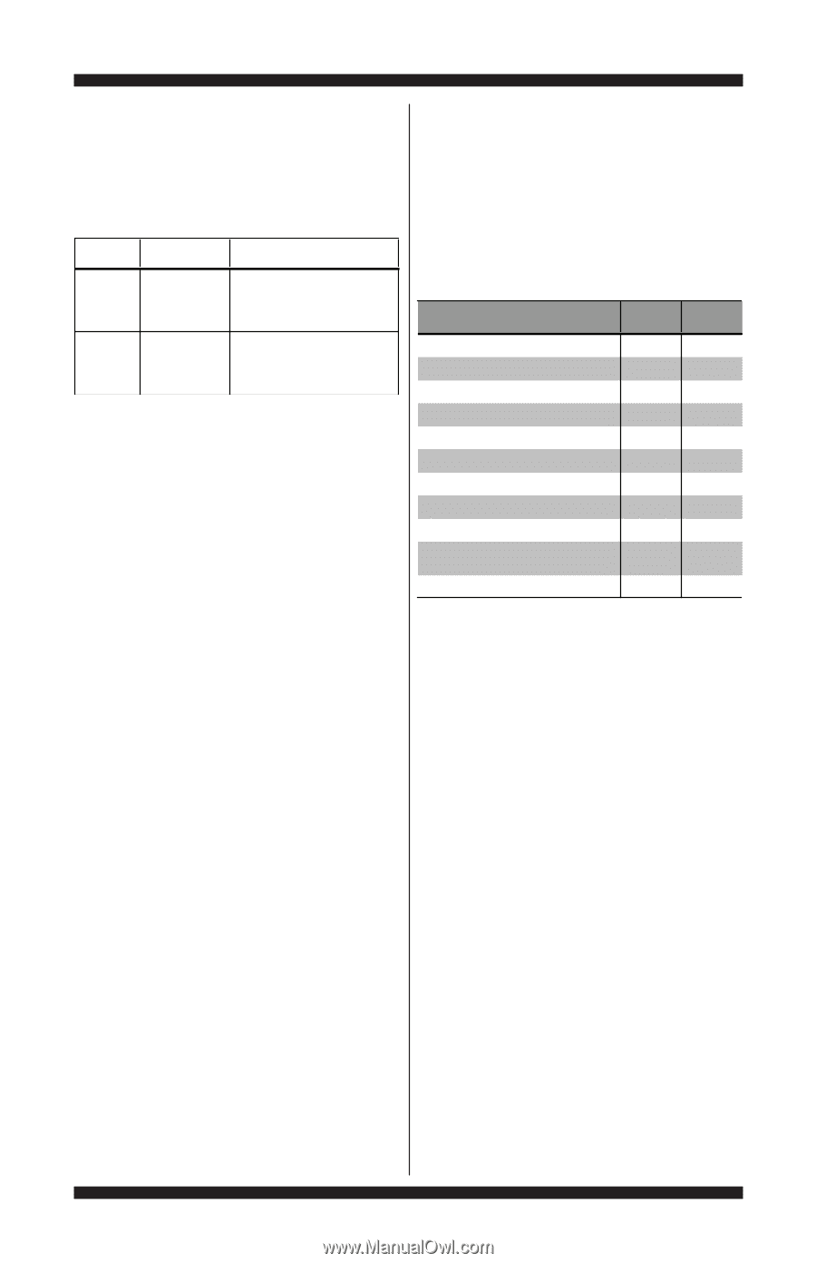
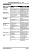
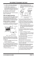
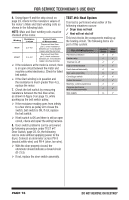
FOR SERVICE TECHNICIAN'S USE ONLY 6. Using figure 9 and the strip circuit on page 23, check for the resistance values of the motor's Main and Start winding coils as shown in the following table. NOTE: Main and Start winding coils must be checked at the motor. Winding Resistance in ohms MAIN 2.5-3.5 START 2.2-3.2 Contact Points of Measurement Disconnect lead from pin 5; check resistance between pin 5 and double copper wire flag terminal. Disconnect lead from pin 3; check resistance between pin 3 and double copper wire flag terminal. If the resistance at the motor is correct, there is an open circuit between the motor and machine control electronics. Check for failed belt switch. If the Start winding is in question and the resistance is much greater than 4 Ω, replace the motor. 7. Check the belt switch by measuring resistance between the two blue wires, as shown in figure 9 on page 15, while pushing up the belt switch pulley. If the resistance reading goes from infinity to a few ohms as pulley arm closes the switch, belt switch is OK. If not, replace the belt switch. If belt switch is OK and there is still an open circuit, check and repair the wiring harness. 8. Door switch problems can be uncovered by following procedure under TEST #7: Door Switch, page 22. Or, the following can be done without applying power to the dryer. Connect an ohmmeter across P8-3 (neutral,white wire) and P8-4 (door, tan wire). With the door properly closed, the ohmmeter should indicate a closed circuit (0-2 Ω). If not, replace the door switch assembly. TEST #4: Heat System This test is performed when either of the following situations occurs: 3 Dryer does not heat 3 Heat will not shut off This test checks the components making up the heating circuit. The following items are part of this system: Part of Heating System Harness/connection Heater relay Thermal cut-off High limit thermostat Heat element assembly Gas valve assembly Centrifugal switch Outlet thermistor Machine control electronics Console electronics and housing assembly Gas supply Electric Dryer no ü ü ü ü Gas Dryer ü ü ü ü no ü ü ü ü ü no ü PAGE 16 DO NOT REMOVE OR DESTROY
-
 1
1 -
2
-
3
-
4
-
5
-
6
-
7
-
8
-
9
-
10
-
 11
11 -
 12
12 -
 13
13 -
 14
14 -
 15
15 -
 16
16 -
 17
17 -
 18
18 -
 19
19 -
 20
20 -
 21
21 -
22
-
23
-
24
-
25
-
26
-
27
-
28
-
29
-
30
-
31
-
32
-
33
-
34
-
35
-
36
-
37
-
38
-
39
-
40
-
41
-
42
-
43
-
44
-
45
-
46
-
47
-
48
-
49
-
50
-
51
-
52
-
53
-
54
-
55
-
56
 |
 |