Maytag MEDB765FW W10240504 - Page 26
Component Locations
 |
View all Maytag MEDB765FW manuals
Add to My Manuals
Save this manual to your list of manuals |
Page 26 highlights
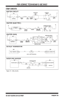
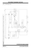
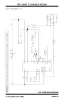
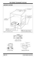
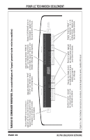
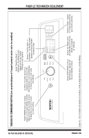
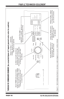
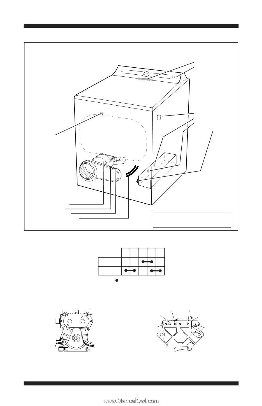
FOR SERVICE TECHNICIAN'S USE ONLY COMPONENT LOCATIONS • ACU (beneath console) • User Interface (UI) Door Switch (Location may vary between models) • Drum Light Assembly • Thermal Cut-off • High Limit Thermostat • Heater Assembly • Motor Assembly • Thermal Fuse • Outlet Thermistor • Moisture Sensor Strips Figure 16 - Component locations. NOTE: Refer to Figure 10b, page 17, for gas dryer component locations. Contacts Function 1M 2M 3M 5M 6M Start Run = Contacts closed Centrifugal Switch (Motor) Black Light Blue White White Light Blue Gas Valve, Gas Dryer Lt. Blue Black-White Red Blue-White (Electric) Blue (Gas) Green-Yellow Red-White Pluggable Drive Motor Switch PAGE 26 DO NOT REMOVE OR DESTROY
-
 1
1 -
2
-
3
-
4
-
5
-
6
-
7
-
8
-
9
-
10
-
11
-
12
-
13
-
14
-
15
-
16
-
17
-
18
-
19
-
20
-
 21
21 -
 22
22 -
 23
23 -
 24
24 -
 25
25 -
 26
26 -
 27
27 -
 28
28 -
 29
29 -
 30
30 -
 31
31 -
32
-
33
-
34
-
35
-
36
-
37
-
38
-
39
-
40
-
41
-
42
-
43
-
44
-
45
-
46
-
47
-
48
-
49
-
50
-
51
-
52
-
53
-
54
-
55
-
56
 |
 |
PAGE 26
FOR SERVICE TECHNICIAN’S USE ONLY
DO NOT REMOVE OR DESTROY
1M
2M
3M
5M
6M
=
Contacts
Function
Start
Run
Contacts closed
Black
Light Blue
Light Blue
White
White
Centrifugal Switch (Motor)
Gas Valve, Gas Dryer
Pluggable Drive Motor Switch
COMPONENT LOCATIONS
• ACU (beneath console)
• User Interface (UI)
• Drum Light Assembly
• Thermal Cut-off
• High Limit Thermostat
• Heater Assembly
Door Switch
(Location may vary
between models)
• Motor Assembly
• Thermal Fuse
• Outlet Thermistor
• Moisture Sensor Strips
Figure 16 - Component locations.
NOTE:
Refer to Figure 10b, page 17,
for gas dryer component locations.
Red
Lt. Blue
Blue-White (Electric)
Blue (Gas)
Green-Yellow
Red-White
Black-White