Maytag MGR6751BDB Installation Instructions - Page 3
Inchp.s.i.liquefiedpetroleum - model
 |
UPC - 719881178714
View all Maytag MGR6751BDB manuals
Add to My Manuals
Save this manual to your list of manuals |
Page 3 highlights
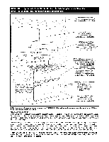
Gas Supply Installationof thisrange mustconformwith localcodesor,in the absenceof localcodes,with the National FuelGas Code,ANSIZ223.1latestedition.In Canadathe rangemust beinstalledin accordance with the currentCGAStandard CAN/CGA-B149- InstallationCodesfor GasBurningAppliancesand Equipmentand/orlocalcodes. In TheCommonwealthOf Massachusetts Thisproductmust be installedbya licensedplumberor gas fitter when installedwithin the Commonwealthof MassachusettsA. "T" handle typemanualgasvalve must be installedin the gas supplyline to this appliance.A flexiblegasconnectorw, hen used,must notexceeda lengthof three(3) feet / 36 inches. Gas leaks may occurin yoursystem and result in a dangerous situation. Gasleaks may not be detectedby smell alone. Gas suppliers recommendyou purchaseand install an ULapproved gas detector. Install and use in accordancewith manufacturerls instructions. A QUALIFIED SERVICEMAN OR GAS APPLIANCE INSTALLER MUST MAKE THE GAS SUPPLYCONNECTION.Leak testing of the appliance shall be conducted by the installer according to the instructions given in Step 6. Apply a non-corrosive leak detection fluid to all joints and fittings in the gas connection between the supply line shut-off valve and the range. Include gas fittings and joints in the range if connections were disturbed during installation. Checkfor leaks! Bubbles appearing around fittings and connections will indicate a leak. If a leak appears, turn off supply line gas shut-off valve, tighten connections, turn on the supply line gas shut off valve, and retest for leaks. CAUTION: NEVERCHECK FOR LEAKS WITH A FLAME. WHEN LEAK CHECKIS COMPLETE,WIPE OFF ALL RESIDUE. NATURALGASSUPPLYLINEMUSTHAVEA NATURALGASSERVICE REGULATORIN. LETPRESSURETOTHISAPPLIANCESHOULDBE REDUCEDTOA MAXIMUMOF 14 INCHESWATERCOLUMN(0.5 POUNDS PERSQUAREINCH(P.S.I.)LIQUEFIEDPETROLEUM(L.P.)/PROPANGEAS SUPPLYLINEMUSTHAVEA L.P.GASPRESSUREREGULATORIN. LET PRESSURETOTHISAPPLIANCESHOULDBEREDUCEDTOA MAXIMUM OF 14 INCHESWATERCOLUMN(0.5 P.S.I.)I.NLETPRESSUREISN EXCESSOF 0.5 P.S.I.CANDAMAGETHEAPPLIANCEPRESSURE REGULATOARND OTHERGASCOMPONENTISN THISAPPLIANCEAND CANRESULTIN A GASLEAK. Gassupply pressure for testing regulator must be at least 1" water column pressure above manifold pressure shown on serial plate. Check Pressure of House Piping System 1. Theapplianceand itsindividual shutoff valve must be disconnectedfrom the gassupply piping system duringany pressuretestingofthat system at testpressures in excess of 1/2 Ibs./sq.in.(3.5 kPa)(13.8 in. water column). 2. Theappliancemustbe isolatedfrom the gassupply piping system by closingits individuaml anualshutoff valve duringany pressure testingofthe gas supply pipingsystem at test pressures equal to or lessthan 1/2 Ibs./sq.in. (3.5 kPa)(13.8 in. water column). A GASSHUT-OFFVALVESHOULDBEPUTIN ANACCESSIBLELOCATION INTHESUPPLYLINEAHEADOFTHE RANGEF, ORTURNINGONAND TURNINGOFFGASSUPPLYR. angeis to be connected to house piping with flexible metal connectors for gas appliances. CONNECTONRUTS MUSTNOTBE CONNECTEDIRECTLTYO PIPETHREADST.HE CONNECTORMSUSTBEINSTALLEDWITHADAPTORSPROVIDEDWITH THECONNECTOR. The house piping and/or range connector used to connect the range to the main gas supply must be clean, free of metal shavings, rust, dirt and liquids (oil or water). Dirt, etc. in the supply lines can work its way into the range manifold and in turn cause failure of the gas valves or controls and clog burners and/or pilot orifices. Always use a new flexible connector.Do not use exsisting flexible connector. NOTE:It is recommendedto use a CSAcertified flexible connectorno longerthan 36" (91.4 cm) with a minimum BTU/HRrating of 88,200. 'If! I " v IV "*,_ I" "! _1 Follow these procedures to remove appliance for servicing: 1. Slide rangeforward to disengagerangefrom the anti-tip bracket. 2. Shut off gassupply to appliance. 3. Disconnecet lectricalsupply to appliance,if equipped. 4. Disconnecgt as supply tubingto appliance. 5. Reverseprocedure to reinstall. If gas line has beendisconnected, THE APPLIANCE checkfor gas leaks after reconnection. 6. To prevent range from accidentallytipping,range mustbe securedto the floor by sliding rear levelinglegintothe anti-tip bracket. NOTEA: qualified servicer should disconnect and reconnect the gas supply. Theservicer MUSTfollow installation instructions provided with the gas appliance connector and the warning label attached to the connector. Whenyour range requires service or replacement parts, contact your dealer or authorized service agency.Pleasegive the complete model and serial number of the range which is located on flip-up plate at the rear of upper left-hand corner or center of backguard. I Your range may not be equipped with some of the features referred to in this manual. I
-
 1
1 -
 2
2 -
 3
3 -
 4
4 -
 5
5 -
 6
6 -
 7
7 -
 8
8 -
 9
9 -
10
-
11
-
12
-
13
-
14
 |
 |