Maytag MGT8775XS Installation Instructions - Page 8
Make Gas Connection - valve
 |
UPC - 883049199559
View all Maytag MGT8775XS manuals
Add to My Manuals
Save this manual to your list of manuals |
Page 8 highlights
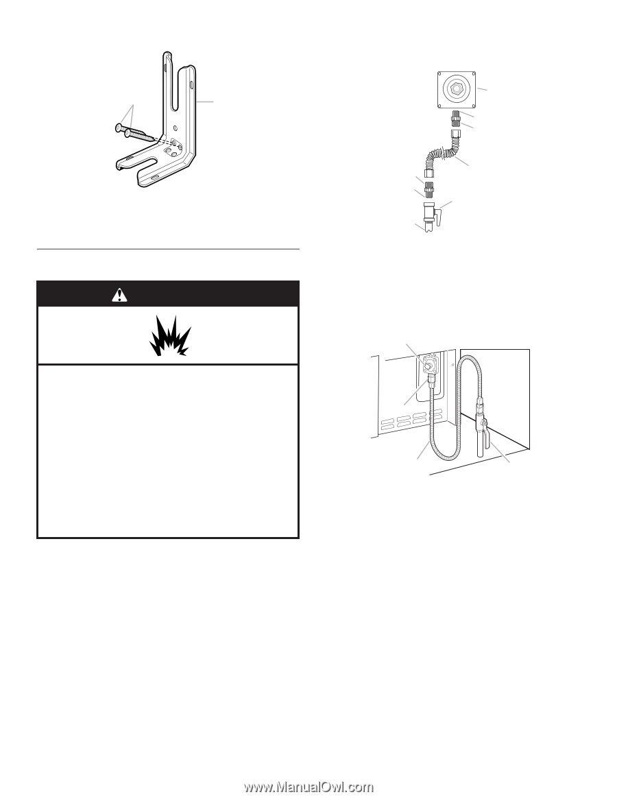
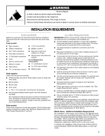
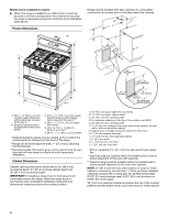
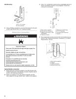
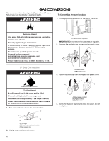
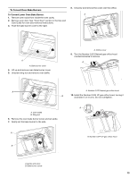
Wall Mounting A B 3. Use a combination wrench and an adjustable wrench to attach the flexible connector to the adapters. Check that connector is not kinked. A B C A. #12 x 1⁵⁄₈" screws B. Anti-tip bracket 5. Using a Phillips screwdriver, mount anti-tip bracket to the wall or floor with the two #12 x 1⁵⁄₈" screws provided. Make Gas Connection WARNING D H G E F A. Gas pressure regulator B. Use pipe-joint compound. C. Adapter (must have ½" male pipe thread) D. Flexible connector E. Manual gas shutoff valve F. ½" or ¾" gas pipe G. Use pipe-joint compound. H. Adapter 4. Gas supply pipe must be located within the shaded area as shown in the "Cabinet Dimensions" illustration in "Location Requirements" section. A Explosion Hazard Use a new CSA International approved gas supply line. Install a shut-off valve. Securely tighten all gas connections. If connected to LP, have a qualified person make sure gas pressure does not exceed 14" (36 cm) water column. Examples of a qualified person include: licensed heating personnel, authorized gas company personnel, and authorized service personnel. Failure to do so can result in death, explosion, or fire. Typical flexible connection 1. Apply pipe-joint compound made for use with LP gas to the smaller thread ends of the flexible connector adapters (see B and G in the following illustration). 2. Attach one adapter to the gas pressure regulator and the other adapter to the gas shutoff valve. Tighten both adapters. Adaptor B C D A. Gas pressure regulator B. Adapter C. Flexible connector D. Manual shutoff valve 8
-
 1
1 -
2
-
 3
3 -
 4
4 -
 5
5 -
 6
6 -
 7
7 -
 8
8 -
 9
9 -
 10
10 -
 11
11 -
 12
12 -
 13
13 -
14
-
15
-
16
-
17
-
18
-
19
-
20
-
21
-
22
-
23
-
24
-
25
-
26
-
27
-
28
-
29
-
30
-
31
-
32
-
33
-
34
-
35
-
36
-
37
-
38
-
39
-
40
 |
 |