Maytag MGT8775XS Installation Instructions - Page 9
Verify Anti-Tip Bracket Location, Level Range, Electronic Ignition System - gas range
 |
UPC - 883049199559
View all Maytag MGT8775XS manuals
Add to My Manuals
Save this manual to your list of manuals |
Page 9 highlights
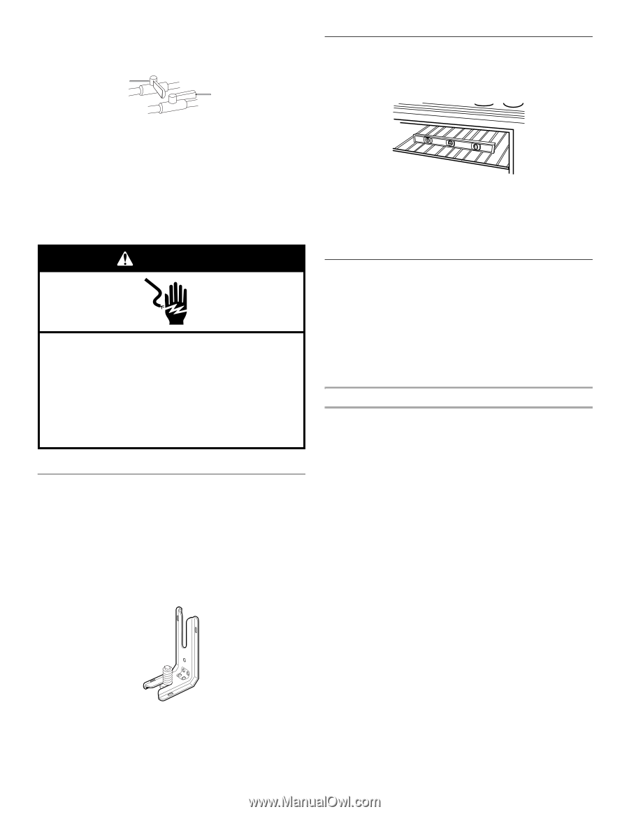
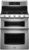
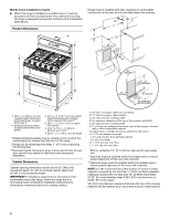
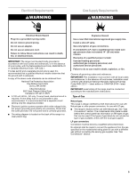
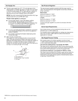
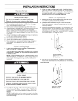
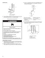
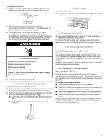
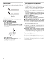
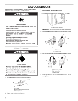
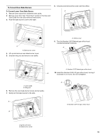
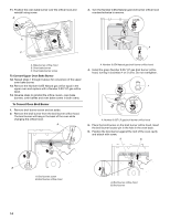
Complete connection 1. Open the manual shutoff valve in the gas supply line. The valve is open when the handle is parallel to the gas pipe. A B Level Range 1. Place rack in oven. 2. Place level on rack and check levelness of range, first side to side; then front to back. A. Closed valve B. Open valve 2. Test all connections by brushing on an approved noncorrosive leak-detection solution. If bubbles appear, a leak is indicated. Correct any leak found. 3. Remove cooktop burner caps and grates from parts package. Align recess in burner caps with pins in burner base. Burner caps should be level when properly positioned. If burner caps are not properly positioned, surface burners will not light. Place burner grates over burners and caps. WARNING Electrical Shock Hazard Plug into a grounded 3 prong outlet. Do not remove ground prong. Do not use an adapter. Do not use an extension cord. Failure to follow these instructions can result in death, fire, or electrical shock. 4. Plug into a grounded 3 prong outlet. Verify Anti-Tip Bracket Location 1. Move range close to cabinet opening. 2. Remove cardboard or hardboard from under the range. Using 2 or more people, gently move range into its final location. 3. To check that the anti-tip bracket is installed, use a flashlight and look underneath the bottom of the range. ■ Look for the anti-tip bracket securely attached to floor or wall. ■ Slide range back so rear range foot is under anti-tip bracket. 3. If range is not level, pull range forward until rear leveling leg is removed from the anti-tip bracket. 4. Use wrench to adjust leveling legs up or down until range is level. Push range back into position. 5. Check that rear leveling leg is engaged in anti-tip bracket. NOTE: Range must be level for satisfactory baking performance. Electronic Ignition System Initial lighting and gas flame adjustments Cooktop and oven burners use pilotless igniters in place of standing pilots. When the cooktop control knob is turned to the "LITE" position, the system creates a spark to light the burner. This sparking continues, as long as the control knob is turned to "LITE." When the oven control is turned to the desired setting, a glow bar igniter heats and ignites the gas. Check Operation of Cooktop Burners Standard Surface Burners Push in and turn each control knob to the "LITE" position. The flame should light within 4 seconds. The first time a burner is lit it may take longer than 4 seconds to light because of air in the gas line. If burners do not light properly: ■ Turn cooktop control knob to the "OFF" position. ■ Check that the range is plugged in and the circuit breaker has not tripped or the household fuse has not blown. ■ Check that the gas shutoff valve is set to the "open" position. ■ Check that burner caps are properly positioned on burner bases. Repeat start-up. If a burner does not light at this point, turn the control knobs to "Off" and contact your dealer or authorized service company for assistance. 9
-
 1
1 -
2
-
3
-
 4
4 -
 5
5 -
 6
6 -
 7
7 -
 8
8 -
 9
9 -
 10
10 -
 11
11 -
 12
12 -
 13
13 -
 14
14 -
15
-
16
-
17
-
18
-
19
-
20
-
21
-
22
-
23
-
24
-
25
-
26
-
27
-
28
-
29
-
30
-
31
-
32
-
33
-
34
-
35
-
36
-
37
-
38
-
39
-
40
 |
 |