McAfee IIP-S03K-NA-100I Product Guide - Page 30
Cabling the Response ports, ► To connect the Response port to a network device:
 |
UPC - 731944579931
View all McAfee IIP-S03K-NA-100I manuals
Add to My Manuals
Save this manual to your list of manuals |
Page 30 highlights
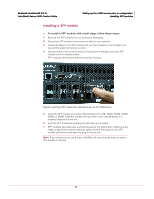
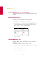
McAfee® IntruShield® IPS 4.1 IntruShield Sensor 3000 Product Guide Attaching cables to the I-3000 Sensor Cabling the Response ports Name Baud rate Number of bits Parity Stop bits Flow Control Setting 9600 8 None 1 None Required settings for the modem are: • 9600 bps port speed • Answer after 1 ring • Save the configuration to NVRAM. Cabling the Response ports The sensor's Response ports are used to send responses to attacks when operating in SPAN or tap mode. You must use a Response port to inject response packets to the switches or routers. ► To connect the Response port to a network device: 1 Plug a Cat 5/Cat 5e cable into the Response port (labeled Rx on the sensor front panel). 2 Connect the other end of the cable to the network device (for example, hub, switch, router) through which you want to respond to attacks. Cabling the Fail-Open Control ports Fail-open functionality for the GE Monitoring ports is accomplished via the Gigabit Fail-open Bypass Kit, sold separately. (Both Copper and Optical versions are available.) For 10/100 Mpbs port speed setting, you are required to use the copper Bypass Kit. For more information, see Gigabit Copper Fail Open Kit Guide. For 1 Gbps port speed setting, you can use either the optical Bypass Kit or the copper Bypass Kit. Installation and troubleshooting instructions for the Kit can be found in the kit's documentation. More details on fail-open operation with the kit is available in Using fail-open hardware (on page 28). For more information, see the documentation that accompanies the Kit. 22
-
 1
1 -
2
-
3
-
4
-
5
-
6
-
7
-
8
-
9
-
10
-
11
-
12
-
13
-
14
-
15
-
16
-
17
-
18
-
19
-
20
-
21
-
22
-
23
-
24
-
 25
25 -
 26
26 -
 27
27 -
 28
28 -
 29
29 -
 30
30 -
 31
31 -
 32
32 -
 33
33 -
 34
34 -
 35
35 -
36
-
37
-
38
 |
 |
