McAfee IIP-S03K-NA-100I Product Guide - Page 35
Cabling I-3000 sensors for Failover, ► To connect two I-3000s for failover:
 |
UPC - 731944579931
View all McAfee IIP-S03K-NA-100I manuals
Add to My Manuals
Save this manual to your list of manuals |
Page 35 highlights
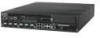
McAfee® IntruShield® IPS 4.1 IntruShield Sensor 3000 Product Guide Attaching cables to the I-3000 Sensor Cabling for SPAN mode fail-over pair even if the Primary sensor has some of its monitoring port pairs in nonInline (TAP/SPAN) mode is provided. For example, in an I-3000, you may have port pairs as 1A-1B, 2A-2B, 3A-3B and 4A4B configured in in-line mode and ports 5A, 5B configured in SPAN mode. Note: TCP reset is not supported when connected in TAP mode. Cabling I-3000 sensors for Failover Monitoring ports 6A-and 6B are the interconnection ports on the I-3000. A failover cable is the only additional hardware required to support failover communication between two I-3000 sensors. When 6A-6B interconnection ports are connected in failover mode with 10 or 100 Mpbs speed value, during failover creation the ports will be updated to 1 Gbps speed value. ► To connect two I-3000s for failover: 1 Plug the cable appropriate for use with your GBIC into port 6A of the active sensor. 2 Connect the other end of the cable to port 6A of the standby sensor. 3 Plug the cable appropriate for use with your GBIC into port 6B of the active sensor. 4 Connect the other end of the cable to port 6B of the standby sensor. Figure 9: Cabling I-3000 sensors for Failover 27
-
 1
1 -
2
-
3
-
4
-
5
-
6
-
7
-
8
-
9
-
10
-
11
-
12
-
13
-
14
-
15
-
16
-
17
-
18
-
19
-
20
-
21
-
22
-
23
-
24
-
25
-
26
-
27
-
28
-
29
-
 30
30 -
 31
31 -
 32
32 -
 33
33 -
 34
34 -
 35
35 -
 36
36 -
 37
37 -
 38
38
 |
 |
