Motorola HT750 Service Manual - Page 54
Lowband Molded Antenna Cut Chart - programming instructions
 |
View all Motorola HT750 manuals
Add to My Manuals
Save this manual to your list of manuals |
Page 54 highlights
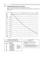
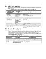
5-6 Radio Tuning, Programming, Cloning, Lowband Antenna Cutting Procedure, PassPort Tone Options, and Diagnostic Functions 5.7 Lowband Molded Antenna Cut Chart This chart is for antenna NAB6064 used with professional radio series. NOTE: The chart below is not drawn to scale. Obtain and use a standard ruler for marking of cutting measurements. TOP OF ANTENNA FREQUENCY IN MHZ 30 31 32 33 34 35 36 37 38 39 40 41 42 43 44 45 46 47 48 49 50 0 0.5 (1.3 cm) 1.0 C U (2.5 cm) T 1.5 (3.8 cm) L E 2.0 N (5.1 cm) G T 2.5 H (6.4 cm) I 3.0 N (7.6 cm) I 3.5 N (8.9 cm) C H 4.0 E (10.2 cm) S 4.5 (11.4 cm) 5.0 (12.7 cm) 5.5 (14.0 cm) Frequency Verification Chart This chart can be used to verify the length or frequency of an antenna already cut. DO NOT use it to make the actual cut. Freq (MHz) 30 32 34 36 38 40 42 44 46 48 50 Final Antenna Length (Inches) 11 9/16 (29.369 cm) 11 7/16 (29.052 cm) 10 5/8 (26.988 cm) 10 (25.400 cm) 9 3/8 (23.813 cm) 8 7/8 (22.543 cm) 8 5/16 (21.114 cm) 7 7/8 (20.003 cm) 7 1/2 (19.050 cm) 7 3/16 (18.256 cm) 6 7/8 (17.463 cm) NOTE: Antenna length measured from top of antenna to bottom of rubber skirt. Cutting Instructions 1. Remove cap from antenna. 2. Measure from top of antenna down to the desired length corresponding with the desired frequency. 3. Mark the antenna, then cut at that mark. 4. To replace the antenna cap, put a small bead of #414 Loctite™ (Motorola part number 1110019B59) around the inside walls of the antenna cap. Place the cap on top of the antenna and seat fully.
-
 1
1 -
2
-
3
-
4
-
5
-
6
-
7
-
8
-
9
-
10
-
11
-
12
-
13
-
14
-
15
-
16
-
17
-
18
-
19
-
20
-
21
-
22
-
23
-
24
-
25
-
26
-
27
-
28
-
29
-
30
-
31
-
32
-
33
-
34
-
35
-
36
-
37
-
38
-
39
-
40
-
41
-
42
-
43
-
44
-
45
-
46
-
47
-
48
-
 49
49 -
 50
50 -
 51
51 -
 52
52 -
 53
53 -
 54
54 -
 55
55 -
 56
56 -
 57
57 -
 58
58 -
 59
59 -
60
-
61
-
62
-
63
-
64
-
65
-
66
-
67
-
68
-
69
-
70
-
71
-
72
-
73
-
74
-
75
-
76
-
77
-
78
-
79
-
80
-
81
-
82
-
83
-
84
-
85
-
86
-
87
-
88
-
89
-
90
-
91
-
92
-
93
-
94
-
95
-
96
 |
 |
