Netgear FE104 Installation Guide - Page 16
Normal/Uplink Push Button
 |
UPC - 606449000832
View all Netgear FE104 manuals
Add to My Manuals
Save this manual to your list of manuals |
Page 16 highlights
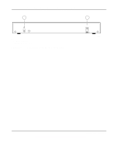
Installation Guide for the Model FE104 and Model FE108 Fast Ethernet Hubs As illustrated in Figure 2-3, two LEDs are positioned at the top corners of each RJ-45 connector. The left indicator is the Link/Rx (receive) LED, and the right indicator is the Part (partition) LED. Both LEDs are described in Table 2-1. Link/Rx Part 184EA Figure 2-3. Link/Rx and Part (partition) LEDs on the RJ-45 ports Normal/Uplink Push Button The Normal/Uplink push button on the front panel of the hub, as illustrated in Figure 2-4, allows you to select uplink (MDI) or normal (MDI-X) wiring for Port 4 on the Model FE104 hub and Port 8 on the Model FE108 hub. Ports 4 and 8 are configured for normal wiring when the push button is in the out position. When the push button is pressed in, Ports 4 and 8 are configured for uplink wiring. Link/Rx Part MODELFE104 Normal/Uplink Link/Rx Partition 1 2 3 4 1 2 3 4 Link/Rx Part Normal/Uplink 5 6 7 8 Model FE104 Figure 2-4. Normal/Uplink push button Model FE108 183EA 2-4 Physical Description
-
 1
1 -
2
-
3
-
4
-
5
-
6
-
7
-
8
-
9
-
10
-
 11
11 -
 12
12 -
 13
13 -
 14
14 -
 15
15 -
 16
16 -
 17
17 -
 18
18 -
 19
19 -
 20
20 -
 21
21 -
22
-
23
-
24
-
25
-
26
-
27
-
28
-
29
-
30
-
31
-
32
-
33
-
34
-
35
-
36
-
37
-
38
-
39
-
40
-
41
-
42
-
43
-
44
 |
 |
