Netgear FE104 Installation Guide - Page 17
Rear Panel - uplink
 |
UPC - 606449000832
View all Netgear FE104 manuals
Add to My Manuals
Save this manual to your list of manuals |
Page 17 highlights
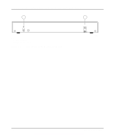
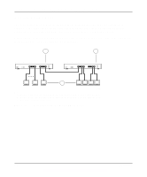
Installation Guide for the Model FE104 and Model FE108 Fast Ethernet Hubs The Normal/Uplink push button eliminates the need to use a crossover cable for daisy-chaining or cascading. Use the following guidelines to configure Ports 4 and 8 for uplink or normal wiring: • Configure Ports 4 and 8 for normal wiring if the port is to be connected to an uplink-wired device, such as a network station or a PC. • Configure Ports 4 and 8 for uplink wiring if the port is to be connected to a normal-wired device, such as a 100 Mbps switch or another hub. The remaining (normal) ports on the hubs cannot be configured for uplink wiring. If you are using one of these ports to connect to another normal port, you must use an RJ-45 crossover cable to connect the two ports (refer to Appendix C, "Fast Ethernet and Cabling Guidelines," for information on the crossover and straight-through cables). Rear Panel As illustrated in Figure 2-5 and Figure 2-6, the rear panel of each hub has a grounding clip and a DC power receptacle that is provided for connection to the supplied DC power adapter. 1 2 12 Vdc 1.2A -+ Key: 1 = Grounding clip 2 = DC power receptacle Figure 2-5. Rear panel of the Model FE104 hub 196EA Physical Description 2-5
-
 1
1 -
2
-
3
-
4
-
5
-
6
-
7
-
8
-
9
-
10
-
11
-
 12
12 -
 13
13 -
 14
14 -
 15
15 -
 16
16 -
 17
17 -
 18
18 -
 19
19 -
 20
20 -
 21
21 -
 22
22 -
23
-
24
-
25
-
26
-
27
-
28
-
29
-
30
-
31
-
32
-
33
-
34
-
35
-
36
-
37
-
38
-
39
-
40
-
41
-
42
-
43
-
44
 |
 |
