Netgear FE104 Installation Guide - Page 7

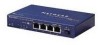
s, Front panel of the Model FE104 Fast Ethernet Hub - switch

Page 7 highlights

Figures Figure 2-1. Figure 2-2. Figure 2-3. Figure 2-4. Figure 2-5. Figure 2-6. Figure 3-1. Figure 3-2. Figure 5-1. Figure 5-2. Figure 5-3. Figure B-1. Figure C-1. Figure C-2. Figure C-3. Front panel of the Model FE104 Fast Ethernet Hub 2-1 Front panel of the Model FE108 Fast Ethernet Hub 2-2 Link/Rx and Part (partition) LEDs on the RJ-45 ports 2-4 Normal/Uplink push button 2-4 Rear panel of the Model FE104 hub 2-5 Rear panel of the Model FE108 hub 2-6 Daisy-chaining two Model FE108 hubs 3-4 Connecting multiple hubs 3-5 Model FE104 and Model FE108 hubs as standalone hubs 5-2 Using the Model FE104 hub to migrate your network to 100 Mbps .........5-3 Multiport switch with Fast Ethernet backbone 5-4 RJ-45 connector B-1 Straight-through twisted pair cable C-4 Crossover twisted pair cable C-4 Category 5 UTP patch cable with male RJ-45 connector at each end ... C-5 Figures vii

  • 1
  • 2
  • 3
  • 4
  • 5
  • 6
  • 7
  • 8
  • 9
  • 10
  • 11
  • 12
  • 13
  • 14
  • 15
  • 16
  • 17
  • 18
  • 19
  • 20
  • 21
  • 22
  • 23
  • 24
  • 25
  • 26
  • 27
  • 28
  • 29
  • 30
  • 31
  • 32
  • 33
  • 34
  • 35
  • 36
  • 37
  • 38
  • 39
  • 40
  • 41
  • 42
  • 43
  • 44

Figures
vii
Figures
Figure 2-1.
Front panel of the Model FE104 Fast Ethernet Hub
................................
2-1
Figure 2-2.
Front panel of the Model FE108 Fast Ethernet Hub
................................
2-2
Figure 2-3.
Link/Rx and Part (partition) LEDs on the RJ-45 ports
.............................
2-4
Figure 2-4.
Normal/Uplink push button
......................................................................
2-4
Figure 2-5.
Rear panel of the Model FE104 hub
........................................................
2-5
Figure 2-6.
Rear panel of the Model FE108 hub
........................................................
2-6
Figure 3-1.
Daisy-chaining two Model FE108 hubs
....................................................
3-4
Figure 3-2.
Connecting multiple hubs
.........................................................................
3-5
Figure 5-1.
Model FE104 and Model FE108 hubs as standalone hubs
.....................
5-2
Figure 5-2.
Using the Model FE104 hub to migrate your network to 100 Mbps
.........
5-3
Figure 5-3.
Multiport switch with Fast Ethernet backbone
..........................................
5-4
Figure B-1.
RJ-45 connector
......................................................................................
B-1
Figure C-1.
Straight-through twisted pair cable
.........................................................
C-4
Figure C-2.
Crossover twisted pair cable
...................................................................
C-4
Figure C-3.
Category 5 UTP patch cable with male RJ-45 connector at each end ... C-5