Netgear FE108 Installation Guide - Page 13
Physical Description, Front Panel - model
 |
UPC - 606449000894
View all Netgear FE108 manuals
Add to My Manuals
Save this manual to your list of manuals |
Page 13 highlights
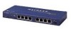
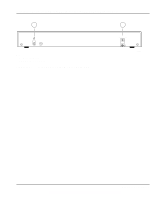
Chapter 2 Physical Description This chapter is divided into sections on the front and rear panel components of the Model FE104 and Model FE108 hubs. Use the key at the bottom of each illustration to identify the associated component. Front Panel The front panel contains the LEDs, RJ-45 100BASE-TX port connectors, and Normal/Uplink push button. Figure 2-1 shows the front panel of the Model FE104 hub, and Figure 2-2 shows the front panel of the Model FE108 hub. 1 2 3 4 5 Pwr Col 100BASE-TX FAST ETHERNET HUB FE104 100 Mbps F AST 1 10 20 >30 Utilization % Link/Rx Part Normal/Uplink 1 2 3 4 Key: 1 = Pwr (power) LED 2 = Col (collision) LED 3 = Utilization % LEDs 4 = RJ-45 ports with Link/Rx and Part (partition) LEDs on each port 5 = Normal/Uplink push button 186EA Figure 2-1. Front panel of the Model FE104 Fast Ethernet Hub Physical Description 2-1
-
 1
1 -
2
-
3
-
4
-
5
-
6
-
7
-
 8
8 -
 9
9 -
 10
10 -
 11
11 -
 12
12 -
 13
13 -
 14
14 -
 15
15 -
 16
16 -
 17
17 -
 18
18 -
19
-
20
-
21
-
22
-
23
-
24
-
25
-
26
-
27
-
28
-
29
-
30
-
31
-
32
-
33
-
34
-
35
-
36
-
37
-
38
-
39
-
40
-
41
-
42
-
43
-
44
 |
 |
