Netgear FE108 Installation Guide - Page 15
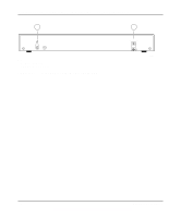
RJ-45 100BASE-TX Ports, certified connector. Refer to Appendix C - power supply
 |
UPC - 606449000894
View all Netgear FE108 manuals
Add to My Manuals
Save this manual to your list of manuals |
Page 15 highlights
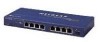
Installation Guide for the Model FE104 and Model FE108 Fast Ethernet Hubs Table 2-1 describes each LED on the front panel of the hub. Table 2-1. LED descriptions Label Pwr Col Color Green Yellow Activity On Blinking Link/Rx Part Green Yellow On Blinking On Utilization % Green On Description Power is supplied to the hub. There is data collision on the network. Note that occasional collisions are normal. The link between this port and the connecting port is good. There is incoming data on the port. The port is being partitioned because of excessive collisions or jabber conditions. Four LEDs indicate whether the percentage of data utilization on the hub or stack of hubs is 1%, 10%, 20%, or more than 30%. RJ-45 100BASE-TX Ports The front panel of the Model FE104 hub provides four RJ-45 100BASE-TX ports, and the Model FE108 provides eight RJ-45 100BASE-TX ports. These standard RJ-45 connectors accept 2-pair Category 5 UTP cable or 4-pair Category 5 UTP cable (100BASE-TX networks require only 2-pair wiring). The RJ-45 interface is an 8-pin connector. Caution: 100 Mbps operation requires the use of Category 5 UTP cable with a 100 Mbps certified connector. Refer to Appendix C, "Fast Ethernet and Cabling Guidelines," for more information on cabling. An illustration of the RJ-45 connector and a table of pin assignments for the normal (MDI-X) RJ-45 connector and the uplink (MDI) RJ-45 connector are in Appendix B, "RJ-45 Connector Information." Table B-1 provides the pinout information. Physical Description 2-3
-
 1
1 -
2
-
3
-
4
-
5
-
6
-
7
-
8
-
9
-
 10
10 -
 11
11 -
 12
12 -
 13
13 -
 14
14 -
 15
15 -
 16
16 -
 17
17 -
 18
18 -
 19
19 -
 20
20 -
21
-
22
-
23
-
24
-
25
-
26
-
27
-
28
-
29
-
30
-
31
-
32
-
33
-
34
-
35
-
36
-
37
-
38
-
39
-
40
-
41
-
42
-
43
-
44
 |
 |
