Netgear FE108 Installation Guide - Page 42
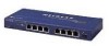
Link/Rx LED, Part partition LED
 |
UPC - 606449000894
View all Netgear FE108 manuals
Add to My Manuals
Save this manual to your list of manuals |
Page 42 highlights
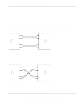
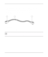
Installation Guide for the Model FE104 and Model FE108 Fast Ethernet Hubs L LEDs Col (collision) 2-3, 4-2 description (table) 2-3 Link/Rx 2-3, 2-4, 3-6 Link/Rx, troubleshooting 4-2 overview 1-2 Part (partition) 2-3, 2-4 Pwr (power) 2-3, 3-6 table 2-3 2-3 troubleshooting 4-2 Utilization % 2-3, 3-6 Link/Rx LED 2-3, 2-4, 3-6 M MDI wiring. See normal wiring MDI-X wiring. See uplink wiring migration to 100 Mbps 1-1, 5-2 multiple hub installation 3-4 N network adapter cards, troubleshooting 4-2 normal wiring 2-4, 2-5, 4-2, C-4 Normal/Uplink push button 1-2, 2-1, 2-2, 2-4, 4-2 O operating conditions 3-1 P package contents 3-2 Part (partition) LED 2-3, 2-4 patch panel C-3, C-5 Port 4 configuring 2-4 pinout information (table) B-2 troubleshooting 4-2 Port 8 configuring 2-4 pinout information (table) B-2 troubleshooting 4-2 ports, RJ-45 2-1, 2-2, 2-3, 2-4 power requirements 3-1 Pwr (power) LED 2-1, 2-3, 3-6 R rear panel 2-5 requirements access 3-1 cabling 2-3, 3-3, C-2 humidity 3-1 operating conditions 3-1 power 3-1 temperature 3-1 ventilation 3-1 wiring 3-1 RJ-45 connector pinouts (table) B-2 troubleshooting 4-1 using for patch cables C-5 RJ-45 ports 2-3, 2-4 2 Index
-
 1
1 -
2
-
3
-
4
-
5
-
6
-
7
-
8
-
9
-
10
-
11
-
12
-
13
-
14
-
15
-
16
-
17
-
18
-
19
-
20
-
21
-
22
-
23
-
24
-
25
-
26
-
27
-
28
-
29
-
30
-
31
-
32
-
33
-
34
-
35
-
36
-
 37
37 -
 38
38 -
 39
39 -
 40
40 -
 41
41 -
 42
42 -
 43
43 -
 44
44
 |
 |
