Netgear FS728TLP Hardware Installation Guide - Page 10
Back Panel, LEDs
 |
View all Netgear FS728TLP manuals
Add to My Manuals
Save this manual to your list of manuals |
Page 10 highlights
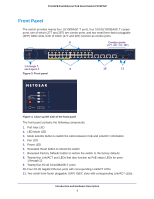
ProSAFE Fast Ethernet PoE Smart Switch FS728TLP Back Panel The back panel provides a 100-240 VAC/50-60 Hz universal power inlet, which is a standard AC power receptacle that accommodates the supplied power cord. Figure 5. Back panel LEDs The following table describes the LEDs. Table 1. LED descriptions Port LED PoE Max LED Mode (Not applicable, system LEDs) Fan Power Ports 1 through 12 (one LED PoE for each PoE port) Note: The LED mode selector button needs to be in the PoE mode. Designation • Off. At least 7W of PoE power is available to connect another powered device (PD). • Solid yellow. Less than 7W of PoE power is available. • Blinking yellow. The PoE Max LED was active in the previous two minutes. • Solid green. The Link/ACT LEDs for the ports indicate Link/ACT status. • Solid yellow. The Link/ACT LEDs for the ports indicate PoE status. The PoE status is displayed for ports 1 through 12 only. • Off. The fan is operating normally. • Solid yellow. A fan failure has occurred. • Off. Power is disconnected. • Solid green. Power is supplied to the switch and the switch is operating normally. • Solid yellow. The switch is starting and not yet ready for operation. • Off. No PoE powered device (PD) is connected. • Solid green. The PoE PD is connected and the port is supplying power successfully. • Solid yellow. One of the following failures prevented power from being supplied to the PD: - Short circuit on the PoE power circuit - PoE power demand exceeds the available power - PoE current exceeds classification of the PD - Out of proper voltage band (44-57 VDC) Introduction and Hardware Description 10
-
 1
1 -
2
-
3
-
4
-
 5
5 -
 6
6 -
 7
7 -
 8
8 -
 9
9 -
 10
10 -
 11
11 -
 12
12 -
 13
13 -
 14
14 -
 15
15 -
16
-
17
-
18
-
19
-
20
-
21
-
22
-
23
 |
 |
