Netgear FS750AT FS750 Reference Manual - Page 18
LED Mode Button and LED Descriptions
 |
UPC - 606449028058
View all Netgear FS750AT manuals
Add to My Manuals
Save this manual to your list of manuals |
Page 18 highlights
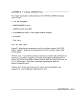
LED Mode Button and LED Descriptions LEDs on the front panels of the FS726 and FS750 Switches provide a quick and accurate display of port operation. Users can clearly identify the status of each port for link and by toggling the LED Mode button through the associated categories speed, activity, collision, and duplex mode . Table 2-1 summarizes the LEDs on the FS726 and FS750 Switches. A detailed description of the LEDs follows the table. Table 2-1. Front Panel LEDs Label Power Link Mode in: Max Spd 10/100 Mbps Port Color Green Off Green Off Green Module Bay Port Green Mode in: Activity / Collision Green Yellow Mode in: FDX Green Yellow Activity On On Description Power is supplied to the switch. Power is disconnected Port has a valid link connection. A valid link has not been established on the port. On Port has made a 100 Mbps connection. Off Port has made a 10 Mbps connection. On Port has a valid 1000 Mbps (1 Gbps) link connection Off A valid link has not been established on the port. Blinking Blinking On On Data transmission is occurring on the port. Data collision is occurring on the port. The rate at which this LED blinks corresponds to the number of collisions. When a collision occurs, the connected device pauses and transmits again after waiting a specified time. Port is operating in full-duplex mode. Port is operating in half-duplex mode. physical description 2-4
-
 1
1 -
2
-
3
-
4
-
5
-
6
-
7
-
8
-
9
-
10
-
11
-
12
-
 13
13 -
 14
14 -
 15
15 -
 16
16 -
 17
17 -
 18
18 -
 19
19 -
 20
20 -
 21
21 -
 22
22 -
 23
23 -
24
-
25
-
26
-
27
-
28
-
29
-
30
-
31
-
32
-
33
-
34
-
35
-
36
-
37
-
38
-
39
-
40
-
41
-
42
-
43
-
44
-
45
-
46
-
47
-
48
-
49
-
50
-
51
-
52
 |
 |
