Netgear FS752TP FS752TP Hardware Installation Guide
Netgear FS752TP Manual
 |
View all Netgear FS752TP manuals
Add to My Manuals
Save this manual to your list of manuals |
Netgear FS752TP manual content summary:
- Netgear FS752TP | FS752TP Hardware Installation Guide - Page 1
FS752TP Smart Switch Hardware Installation Guide 350 East Plumeria Drive San Jose, CA 95134 USA May 2011 202-10813-01 v1.0 - Netgear FS752TP | FS752TP Hardware Installation Guide - Page 2
this manual, visit the Support website at http://support.netgear.com . Phone (US & Canada only): 1-888-NETGEAR Phone (Other Countries): Check the list of phone numbers at http://support.netgear.com/app/answers/detail/a_id/984 Trademarks NETGEAR, the NETGEAR logo, ReadyNAS, ProSafe, ProSecure, Smart - Netgear FS752TP | FS752TP Hardware Installation Guide - Page 3
2 Physical Description FS752TP Front-Panel and Back-Panel Configuration 10 LED Designations 12 System LEDs 12 Port LEDs 13 Device Hardware Interfaces 15 RJ-45 Ports 15 SFP Ports 15 Reset Button 16 Factory Defaults Button 16 Chapter 3 Applications Desktop Switching 18 Chapter 4 Installation - Netgear FS752TP | FS752TP Hardware Installation Guide - Page 4
FS752TP Smart Switch Appendix B Technical Specifications Appendix C Notification of Compliance Index 4 - Netgear FS752TP | FS752TP Hardware Installation Guide - Page 5
1. Introduction 1 Congratulations on the purchase of your NETGEAR® ProSafeTM FS752TP Smart Switch! Your FS752TP switch is a state-of-the-art, high-performance, IEEE-compliant network solution designed for users who require a large number of ports and want the power of Gigabit connectivity to - Netgear FS752TP | FS752TP Hardware Installation Guide - Page 6
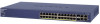
FS752TP Smart Switch Overview The NETGEAR FS752TP Smart Switch has: • 48 Fast Ethernet RJ45 PoE ports with auto sensing, supporting 10/100M speed. Ports 1-4 provide maximum power of 30W and ports 5-48 provide maximum power of 15.4W. The total PoE power budge is 384W. • 2 Gigabit combo ports with - Netgear FS752TP | FS752TP Hardware Installation Guide - Page 7
entry and dynamic MAC addresses learning. • VLANs • IEEE 802.1Q up to 128 VLAN entries. • Protected ports functionality which is similar to Port based VLANs. • 802.3ad Link Aggregation. • Setting LAGs manually or dynamically using LACP. • Auto-Voice VLAN. • Port mirroring (many to one), including - Netgear FS752TP | FS752TP Hardware Installation Guide - Page 8
Contents Verify that the package contains the following: • FS752TP Smart Switch • Rubber footpads for tabletop installation • Rackmounting kits • Power cord • Installation guide • Smart Switch Resource CD with NETGEAR Smart Control Center and User's Manual If any item is missing or damaged, contact - Netgear FS752TP | FS752TP Hardware Installation Guide - Page 9
2. Physical Description 2 This chapter describes the FS752TP Smart Switch hardware features. Topics include: • FS752TP Front-Panel and Back-Panel Configuration • LED Designations • Device Hardware Interfaces 9 - Netgear FS752TP | FS752TP Hardware Installation Guide - Page 10
the front panel of the NETGEAR FS752TP. Power/Status LED Factory Defaults Button Reset Button 10/100 Mbps copper ports Combo Ports Figure 2. Front Panel The front panel contains the following: • 48 RJ-45 connectors for 10/100 Mbps autosensing Fast Ethernet switching ports • Two SFP combo Gigabit - Netgear FS752TP | FS752TP Hardware Installation Guide - Page 11
FS752TP Smart Switch Figure 3. Back Panel The back panel contains a power connector. Power Connector Physical Description 11 - Netgear FS752TP | FS752TP Hardware Installation Guide - Page 12
FS752TP Smart Switch LED Designations The front panel supports a number of LEDs that indicate basic status of the unit and individual ports, Yellow - Indicates the PoE MAX LED was active in the previous two minutes. • Off - There is at least 7 watts of PoE power available for another device - Netgear FS752TP | FS752TP Hardware Installation Guide - Page 13
FS752TP Smart Switch LED LED Mode Designation • Solid Green- Indicates port LEDs are in Ethernet mode. • Solid Yellow - Indicates port LEDs are in PoE mode. Port LEDs 10/100M Fast Ethernet Ports Each 10/100M port has a single bicolor LED. There are two operating modes, Ethernet mode and PoE mode - Netgear FS752TP | FS752TP Hardware Installation Guide - Page 14
FS752TP Smart Switch 10/100/1000M Gigabit Ports Each 10/100/1000M copper port has one LED per port. The possible states and associated meaning are shown in the table below. Table 3. Link/ACT/Speed LED State Designation Solid Green A valid 1000 Mbps link is established on the port. Blinking - Netgear FS752TP | FS752TP Hardware Installation Guide - Page 15
to a PC) or an "uplink" connection (such as when connecting the port to a router, switch, or hub). • Configures the RJ-45 port to enable communications with the attached device, without requiring user intervention. In this way, the Auto Uplink technology compensates for setting uplink connections - Netgear FS752TP | FS752TP Hardware Installation Guide - Page 16
the Factory Defaults button, insert a device such as a paper clip into the opening to press the recessed button for over two seconds. The switch restores all settings to the factory default configuration and then resets. Settings including the password, VLAN settings, and port configurations are - Netgear FS752TP | FS752TP Hardware Installation Guide - Page 17
3. Applications 3 Your FS752TP Smart Switch is designed to provide flexibility in configuring your network connections. It can be used as your only network traffic-distribution device or with 10 Mbps, 100 Mbps, and 1000 Mbps hubs and switches. 17 - Netgear FS752TP | FS752TP Hardware Installation Guide - Page 18
that enables users to have 100 Mbps access to a file server. With full-duplex enabled, the switch uplink port (port 49 to 52) connected to the server can provide 2000 Mbps throughput. Power Fan PoE Max LED Mode Yellow=PoE Green=Link/ACT Select Reset Factory Defaults 1 2 3 4 5 6 7 8 9 10 - Netgear FS752TP | FS752TP Hardware Installation Guide - Page 19
Installation 4 This chapter describes the installation procedures for your FS752TP Smart Switch. Switch installation involves the following steps: Step 1: Preparing the Site Rackmount Considerations Step 2: Installing the Switch Step 3: Checking the Installation Step 4: Connecting Devices to the - Netgear FS752TP | FS752TP Hardware Installation Guide - Page 20
FS752TP Smart Switch Step 1: Preparing the Site Before you install the switch, ensure the operating environment meets the site requirements in the following table. Characteristics Requirements Mounting • Desktop installations - Provide a flat table or shelf surface. • Rackmount installations - - Netgear FS752TP | FS752TP Hardware Installation Guide - Page 21
FS752TP Smart Switch Characteristics Requirements Circuit Overloading Consideration should be given to supply wiring. Appropriate consideration of equipment nameplate ratings should be used when addressing this concern. Reliable Earthing Reliable earthing of rack-mounted equipment should be - Netgear FS752TP | FS752TP Hardware Installation Guide - Page 22
FS752TP Smart Switch Step 3: Checking the Installation Before applying power to the switch, perform the following steps: • Inspect the equipment thoroughly. • Verify that all cables are installed correctly. • Check cable routing to make sure cables are not damaged - Netgear FS752TP | FS752TP Hardware Installation Guide - Page 23
to connect PCs to the switch's RJ-45 ports. The FS752TP contains Auto Uplink technology, which allows the attaching of devices using either straight-through or crossover cables. Power Fan PoE Max LED Mode Yellow=PoE Green=Link/ACT Select Reset Factory Defaults 1 2 3 4 5 6 7 8 9 10 11 12 - Netgear FS752TP | FS752TP Hardware Installation Guide - Page 24
Yellow=PoE Green=Link/ACT Select Reset Factory Defaults 1 2 3 4 5 6 7 8 9 10 11 12 13 14 15 16 17 18 19 20 21 22 23 24 25 26 27 28 29 30 31 32 33 34 35 36 37 38 39 40 41 42 43 44 45 46 47 48 49F 50F FS752TP 49T 50T 51 52 Ports 1-48, Link - Netgear FS752TP | FS752TP Hardware Installation Guide - Page 25
FS752TP Smart Switch Step 6: Applying AC Power The FS752TP Smart Switch does not have an ON/OFF switch. Power must be controlled by the power cord connection. Before connecting the power cord, select an AC outlet that is not controlled by a wall switch, which can turn off power to the switch. After - Netgear FS752TP | FS752TP Hardware Installation Guide - Page 26
time, the Smart Switch can be configured using a Web browser or a program called Smart Control Center. For more information about managing the switch, see the FS752TP Software Administration Manual on the Smart Switch Resource CD. Note: The switch is configured with a default IP address of 192.168 - Netgear FS752TP | FS752TP Hardware Installation Guide - Page 27
A. Troubleshooting A This chapter provides information about troubleshooting the NETGEAR Smart Switch. Topics include the following: • Troubleshooting Chart • Additional Troubleshooting Suggestions 27 - Netgear FS752TP | FS752TP Hardware Installation Guide - Page 28
FS752TP Smart Switch Troubleshooting Chart The following table lists symptoms, causes, and solutions of possible problems. Symptom Cause Solution Power LED is off. No power is received. Check the power cord connections and the connected device. Ensure all cables used are - Netgear FS752TP | FS752TP Hardware Installation Guide - Page 29
If required, verify the integrity of the switch by resetting the switch. To reset the switch, remove the AC power from the switch and then reapply AC power. If the problem continues, contact NETGEAR technical support. In North America, call 1-888-NETGEAR. If you are outside of North America - Netgear FS752TP | FS752TP Hardware Installation Guide - Page 30
Tree Protocol IEEE 802.1X Port Security IEEE 802.1AB LLDP IEEE 802.3s MSTP SNMP v1, v2c, and v3 HTTP and HTTPS Port Mirroring (RX, TX, and Both) IGMP Snooping v1/v2/v3 IEEE 802.1p Class of Service (CoS) SNTP (Simple Network Time Protocol) 3 servers. Disabled by default. Jumbo Frame Support (9K) 30 - Netgear FS752TP | FS752TP Hardware Installation Guide - Page 31
FS752TP Smart Switch Interface 48 Fast Ethernet RJ-45 PoE ports with auto sensing, supporting 10/100M speed. Ports 1-4 provide maximum power of 30W and ports 5-48 provide maximum power of 15.4W. The total PoE power budge is 384W. Two Gigabit combo ports with auto sensing, supporting 10/100/1000M - Netgear FS752TP | FS752TP Hardware Installation Guide - Page 32
FS752TP Smart Switch Electromagnetic Emissions CE Class A, including EN 55022 (CISPR 22), EN 55024, and EN 61000-1 FCC Part 15 Class A VCCI Class A C-Tick KC CCC Safety UL/cUL CE EN 60950-1 CCC CB Technical Specifications 32 - Netgear FS752TP | FS752TP Hardware Installation Guide - Page 33
in conjunction with any other antenna or transmitter. FCC Declaration Of Conformity We, NETGEAR, Inc., 350 East Plumeria Drive, San Jose, CA 95134, declare under our sole responsibility that the FS752TP Smart Switch complies with Part 15 of FCC Rules. Operation is subject to the following two - Netgear FS752TP | FS752TP Hardware Installation Guide - Page 34
. Modifications made to the product, unless expressly approved by NETGEAR, Inc., could void the user's right to operate the equipment. Canadian Department of Communications Radio Interference Regulations This digital apparatus, FS752TP Smart Switch, does not exceed the Class B limits for radio-noise - Netgear FS752TP | FS752TP Hardware Installation Guide - Page 35
Site 20 R Rackmount kit 8 Reset Button 10 RJ-45 Ports 15 RJ-45 ports 6 Rubber footpads 8, 21 S Smart Switch Resource CD 8 Straight-through 15 System LEDs 15 T technical support 2 Temperature 20 trademarks 2 Traffic Control 6 Troubleshooting Chart 28 U User Intervention 15 User's Manual 8 UTP 23 35 - Netgear FS752TP | FS752TP Hardware Installation Guide - Page 36
FS752TP Smart Switch V Ventilation 20 VLAN 6 W Web-based Graphical User Interface 6 36
-
 1
1 -
 2
2 -
 3
3 -
 4
4 -
 5
5 -
 6
6 -
 7
7 -
8
-
9
-
10
-
11
-
12
-
13
-
14
-
15
-
16
-
17
-
18
-
19
-
20
-
21
-
22
-
23
-
24
-
25
-
26
-
27
-
28
-
29
-
30
-
31
-
32
-
33
-
34
-
35
-
36
 |
 |

350 East Plumeria Drive
San Jose, CA 95134
USA
May 2011
202-10813-01
v1.0
FS752TP Smart Switch
Hardware Installation Guide