Netgear FS752TP FS752TP Hardware Installation Guide - Page 24
Step 5: Installing an SFP Transceiver Module, Note
 |
View all Netgear FS752TP manuals
Add to My Manuals
Save this manual to your list of manuals |
Page 24 highlights
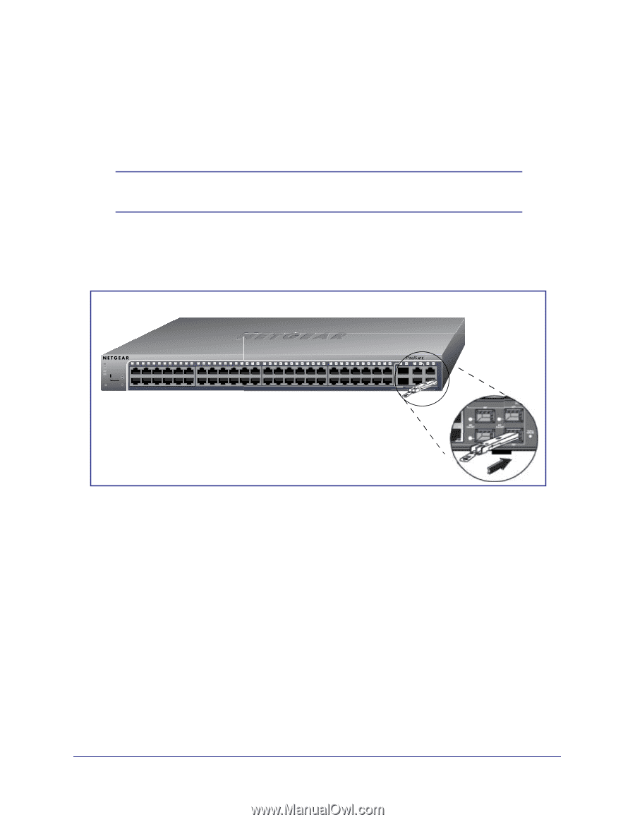
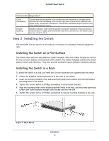
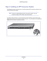
FS752TP Smart Switch Step 5: Installing an SFP Transceiver Module The following procedure describes how to install an optional SFP transceiver module into one of the SFP ports of the switch. Note: Contact your NETGEAR sales office to buy these modules. If you do not want to install an SFP module, skip this procedure. To install an SFP transceiver, insert the transceiver into the SFP port. Press firmly on the flange of the module to seat it securely into the connector. You can install up to two additional Gigabit Ethernet modules using this procedure. Power Fan PoE Max LED Mode Yellow=PoE Green=Link/ACT Select Reset Factory Defaults 1 2 3 4 5 6 7 8 9 10 11 12 13 14 15 16 17 18 19 20 21 22 23 24 25 26 27 28 29 30 31 32 33 34 35 36 37 38 39 40 41 42 43 44 45 46 47 48 49F 50F FS752TP 49T 50T 51 52 Ports 1-48, Link/Act Mode - Green=Link at 100M, Yellow=Link at 10M Blink=ACT Combo Ports Ports 49-52 Link/Act Mode - Green=1G, Yellow=10/100M Blink=ACT Installation 24
-
 1
1 -
2
-
3
-
4
-
5
-
6
-
7
-
8
-
9
-
10
-
11
-
12
-
13
-
14
-
15
-
16
-
17
-
18
-
 19
19 -
 20
20 -
 21
21 -
 22
22 -
 23
23 -
 24
24 -
 25
25 -
 26
26 -
 27
27 -
 28
28 -
 29
29 -
30
-
31
-
32
-
33
-
34
-
35
-
36
 |
 |