Netgear FSM726v2 FSM726v2 Installation Guide - Page 11
Gigabit Ethernet Ports RJ-45 and GBIC module bay
 |
View all Netgear FSM726v2 manuals
Add to My Manuals
Save this manual to your list of manuals |
Page 11 highlights
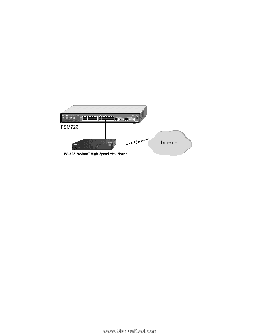
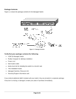
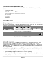
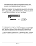
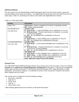
• After ascertaining this information, the switch automatically configures the RJ-45 port to enable communications with the attached device, without requiring user intervention. In this way, the Auto Uplink technology compensates for setting uplink connections, while eliminating concern about whether to use crossover or straight-through cables when attaching devices. Warning! You must use Link Aggregation (a.k.a. Port Trunking) to create multiple links between switches. Using Auto Uplink to create multiple active paths between any two network devices can cause undesirable loops in the network, resulting in an endless broadcast traffic that disables your network. Loops occur when there are alternate routes between two network devices. In Figure 2-3, for example, connecting two RJ-45 ports on a NETGEAR Model FSM726 Managed Switch to a router containing a 4-port switch creates a loop. The Spanning Tree protocol will prevent loops, if that advanced feature is enabled. Figure 2-3. Warning! Creating Redundant Paths between Network Devices Gigabit Ethernet Ports (RJ-45 and GBIC module bay) Your NETGEAR Model FSM726 Managed Switch has two Gigabit Ethernet ports that can be used as either a 1000BASE-T port or as a GBIC module bay. The default setting for those ports are for the built-in RJ-45 connector to be active, but they can be independently configured to activate either the RJ-45 or the GBIC module, enabling multiple combinations of fiber and copper connections. The Gigabit Ethernet ports provide a full-duplex 1000 Mbps (1 Gbps) connection that effectively doubles throughput to 2 Gbps. The GBIC bay accommodates a standard GBIC module, such as the NETGEAR AGM721F 1000BASE-SX GBIC module. This module has an SC connector that is compatible with the IEEE 802.3z 1000BASE-SX standard. Page 10 of 10
-
 1
1 -
2
-
3
-
4
-
5
-
 6
6 -
 7
7 -
 8
8 -
 9
9 -
 10
10 -
 11
11 -
 12
12 -
 13
13 -
 14
14 -
 15
15 -
 16
16 -
17
-
18
-
19
-
20
-
21
-
22
-
23
-
24
-
25
 |
 |