Netgear FSM726v2 FSM726v2 Installation Guide - Page 14
Installation
 |
View all Netgear FSM726v2 manuals
Add to My Manuals
Save this manual to your list of manuals |
Page 14 highlights
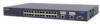
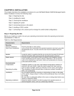
CHAPTER 3: INSTALLATION This chapter describes the installation procedures for your NETGEAR Model FSM726 Managed Switch. Switch installation involves the following steps: Step 1: Preparing the site Step 2: Installing the switch Step 3: Checking the installation Step 4: Applying AC power Step 5: Connecting devices to the switch Step 6: Installing a GBIC module Step 7: Connecting to the console port to manage the switch (initial configuration) Step 1: Preparing the Site Before you install your switch, be sure your operating environment meets the operating environment requirements in Table 3-1. Table 3-1. Site Requirements Characteristics Mounting Desktop installations: Rack-mount installations: Requirements Provide a flat table or shelf surface. Use a 19-inch (48.3-centimeter) EIA standard equipment rack that is grounded and physically secure. You also need the rack-mount kit supplied with your switch. Access Power source Environmental Temperature: Operating humidity: Ventilation: Operating conditions: Locate the switch in a position that lets you access the front panel RJ-45 ports, view the front panel LEDs, and access the rear-panel power connector. Provide a power source within 6 feet (1.8 meters) of the installation location. Power specifications for the switch is shown in Appendix C. Be sure the AC outlet is not controlled by a wall switch, which can accidentally turn off power to the outlet and the switch. Install the switch in a dry area, with ambient temperature between 0 and 40ºC (32 and 104ºF). Keep the switch away from heat sources such as direct sunlight, warm air exhausts, hot-air vents, and heaters. The installation location should have a maximum relative humidity of 90%, non-condensing. Do not restrict airflow by covering or obstructing air inlets on the sides of the switch. Keep at least 2 inches (5.08 centimeters) free on all sides for cooling. Be sure there is adequate airflow in the room or wiring closet where you intend to install the switch. Keep the switch at least 6 ft (1.83 m) away from nearest source of electromagnetic noise, such as a photocopy machine. Page 13 of 13
-
 1
1 -
2
-
3
-
4
-
5
-
6
-
7
-
8
-
 9
9 -
 10
10 -
 11
11 -
 12
12 -
 13
13 -
 14
14 -
 15
15 -
 16
16 -
 17
17 -
 18
18 -
 19
19 -
20
-
21
-
22
-
23
-
24
-
25
 |
 |
