Netgear GS510TP GS510TP Hardware Installation Guide - Page 14
System LEDs, Device Hardware Interfaces, RJ-45 Ports, Reset Button
 |
View all Netgear GS510TP manuals
Add to My Manuals
Save this manual to your list of manuals |
Page 14 highlights
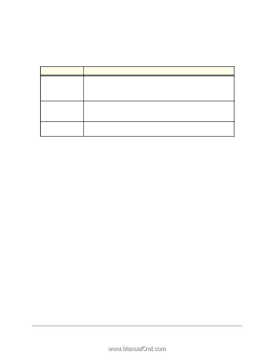
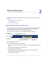
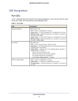
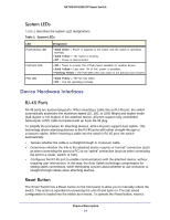
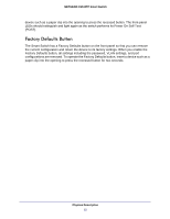
NETGEAR GS510TP Smart Switch System LEDs Table 2 describes the system LED designations. Table 2. System LEDs LED Power/Status LED PoE MAX LED FAN LED Designation • Solid Green = Power is supplied to the switch and the switch is operating normally. • Solid Yellow = The switch is booting. • Off = Power is disconnected. • Off = There is at least 7W of PoE power available for another device. • Solid Yellow = Less than 7W of PoE power is available. • Flashing Yellow = The PoE MAX LED was active in the previous two minutes. • Solid Yellow = The fan has failed. • Off = The fan operating normally. Device Hardware Interfaces RJ-45 Ports RJ-45 ports are autosensing ports. When inserting a cable into an RJ-45 port, the switch automatically ascertains the maximum speed (10, 100, or 1000 Mbps) and duplex mode (half-duplex or full-duplex) of the attached device. All ports support only unshielded twisted-pair (UTP) cable terminated with an 8-pin RJ-45 plug. To simplify the procedure for attaching devices, all RJ-45 ports support Auto Uplink. This technology allows attaching devices to the RJ-45 ports with either straight-through or crossover cables. When inserting a cable into the switch's RJ-45 port, the switch automatically: • Senses whether the cable is a straight-through or crossover cable. • Determines whether the link to the attached device requires a "normal" connection (such as when connecting the port to a PC) or an "uplink" connection (such as when connecting the port to a router, switch, or hub). • Configures the RJ-45 port to enable communications with the attached device, without requiring user intervention. In this way, the Auto Uplink technology compensates for setting uplink connections, while eliminating concern about whether to use crossover or straight-through cables when attaching devices. Reset Button The Smart Switch has a Reset button on the front panel to allow you to manually reboot the switch. This action is equivalent to powering the unit off and back on. The last saved configuration is loaded into the switch as it resets. To operate the Reset button, insert a Physical Description 14
-
 1
1 -
2
-
3
-
4
-
5
-
6
-
7
-
8
-
 9
9 -
 10
10 -
 11
11 -
 12
12 -
 13
13 -
 14
14 -
 15
15 -
 16
16 -
 17
17 -
 18
18 -
 19
19 -
20
-
21
-
22
-
23
-
24
-
25
-
26
-
27
-
28
-
29
-
30
-
31
-
32
 |
 |