Netgear GSM7212P GSM5212P/GSM7212P/GSM7212F/GSM7224P Hardware Installation Gui
Netgear GSM7212P Manual
 |
View all Netgear GSM7212P manuals
Add to My Manuals
Save this manual to your list of manuals |
Netgear GSM7212P manual content summary:
- Netgear GSM7212P | GSM5212P/GSM7212P/GSM7212F/GSM7224P Hardware Installation Gui - Page 1
Managed Switch Hardware Installation Guide Models: GSM5212P GSM7212F GSM7212P GSM7224P 350 East Plumeria Drive San Jose, CA 95134 USA September 2011 202-10889-01 v1.0 - Netgear GSM7212P | GSM5212P/GSM7212P/GSM7212F/GSM7224P Hardware Installation Gui - Page 2
East Plumeria Drive San Jose, CA 95134 USA E-mail: [email protected] Website: http://www.netgear.com Phone: 1-888-NETGEAR, for US & Canada only. For other countries, see your Support information card. Trademarks NETGEAR, the NETGEAR logo, ProSafe, Smart Wizard, and Auto Uplink are trademarks or - Netgear GSM7212P | GSM5212P/GSM7212P/GSM7212F/GSM7224P Hardware Installation Gui - Page 3
16 Connecting Equipment to the Switch 17 RJ-45 Ports 17 Connecting a Console to the Switch 18 Chapter 3 Troubleshooting Troubleshooting Chart 20 Additional Troubleshooting Suggestions 21 Appendix A Technical Specifications Specifications 22 Appendix B Default Configuration Settings Appendix - Netgear GSM7212P | GSM5212P/GSM7212P/GSM7212F/GSM7224P Hardware Installation Gui - Page 4
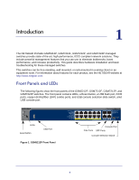
The NETGEAR ProSafe GSM5212P, GSM7212F, GSM7212P, and GSM7224P managed switches provide state-of-the-art, high-performance, IEEE-compliant network solutions. They include powerful management features that you can use to eliminate bottlenecks, boost performance, and increase productivity. This guide - Netgear GSM7212P | GSM5212P/GSM7212P/GSM7212F/GSM7224P Hardware Installation Gui - Page 5
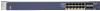
NETGEAR Managed Switch USB Port LEDs Reset button Figure 2. GSM7212F Front Panel USB Port LEDs Reset button Figure 3. GSM7212P Front Panel USB Port LEDs Reset button Figure 4. GSM7224P Front Panel RJ45 and Fiber Ports Console Port Console Selection Switch PoE Ports SFP Ports Console Port - Netgear GSM7212P | GSM5212P/GSM7212P/GSM7212F/GSM7224P Hardware Installation Gui - Page 6
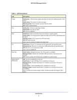
power) Solid Yellow: The internal power supply has failed and the RPS is providing power to switch. Blinking Yellow: RPS is present but RPS has failed Off: RPS Disconnected Note: only for GSM7212F,GSM7212P,GSM7224P Solid Green: PD port 1 is connected to PSE getting 802.3at specified power Blinking - Netgear GSM7212P | GSM5212P/GSM7212P/GSM7212F/GSM7224P Hardware Installation Gui - Page 7
NETGEAR Managed Switch Table 1. LED Descriptions (Continued) LED PoE Description OFF: No PoE powered rear panels have a console port, a redundant power supply connector (only for GSM7212F, GSM7212P, and GSM7224P), and a standard AC power receptacle for the supplied power cord. Introduction 7 - Netgear GSM7212P | GSM5212P/GSM7212P/GSM7212F/GSM7224P Hardware Installation Gui - Page 8
NETGEAR Managed Switch Lock Console Port Figure 5. GSM5212P Rear Panel AC Power Connector Console RPS Port Power Supply Connector Lock Figure 6. GSM7212F, GSM7212P, and GSM7224P Rear Panels AC Power Connector Safety Instructions and follow service markings. - Do not service any product - Netgear GSM7212P | GSM5212P/GSM7212P/GSM7212F/GSM7224P Hardware Installation Gui - Page 9
system components, and never operate the product in a wet environment. If the system gets wet, see the appropriate section in your troubleshooting guide or contact your trained service provider. • Do not push any objects into the openings of your system. Doing so can cause fire or electric shock by - Netgear GSM7212P | GSM5212P/GSM7212P/GSM7212F/GSM7224P Hardware Installation Gui - Page 10
NETGEAR Managed Switch • Position system cables and power cables carefully; route cables so that they cannot be stepped on or tripped over. Be sure that nothing rests on - Netgear GSM7212P | GSM5212P/GSM7212P/GSM7212F/GSM7224P Hardware Installation Gui - Page 11
includes these documents or links to access them: - ProSafe Managed Switch CLI Manual, Version 9.0.2 - NETGEAR Managed Switch Administration Guide - NETGEAR Managed Switch Installation Guide - This Hardware Installation Guide • ProSafe NMS200 Network Management System 30-day trial DVD Protecting - Netgear GSM7212P | GSM5212P/GSM7212P/GSM7212F/GSM7224P Hardware Installation Gui - Page 12
NETGEAR Managed Switch 1. When unpacking a static-sensitive component from its shipping carton, leave it Check the contents of the boxes to make sure that all items are present before installing the switch. 1. Place the container on a clean flat surface and cut all straps securing the container. - Netgear GSM7212P | GSM5212P/GSM7212P/GSM7212F/GSM7224P Hardware Installation Gui - Page 13
NETGEAR Managed Switch The site where you install the switch may greatly affect its performance. Before installing the switch or switches, make sure that the chosen installation location meets the following site requirements. Table 2. Site Requirements for Switch Location Requirements Mounting - Netgear GSM7212P | GSM5212P/GSM7212P/GSM7212F/GSM7224P Hardware Installation Gui - Page 14
NETGEAR Managed Switch 2. Use the provided Phillips head screws to fasten the brackets to the sides of the switch. mounting bracket Figure 7. Installing the Switch in a Rack 3. Tighten the screws with a No. 1 Phillips screwdriver to secure each bracket. 4. Align the bracket and rack holes. Use two - Netgear GSM7212P | GSM5212P/GSM7212P/GSM7212F/GSM7224P Hardware Installation Gui - Page 15
NETGEAR Managed Switch 8. Tighten the screws with a No. 2 Phillips screwdriver to secure the switch in the wall. Figure 8. Installing the Switch on a Wall Check the Installation Before you apply power, perform the following checks: 1. Inspect the equipment thoroughly. 2. Verify that all cables are - Netgear GSM7212P | GSM5212P/GSM7212P/GSM7212F/GSM7224P Hardware Installation Gui - Page 16
1. Connect one end of the AC power adapter cable to the rear of the switch, and the other end to a grounded 3-pronged support IEEE802.1at, the GSM5212P may not operate correctly. GSM7224P and GSM7212P switches support IEEE 802.1at on all ports. 2. Check the Power LED on the front panel of the switch - Netgear GSM7212P | GSM5212P/GSM7212P/GSM7212F/GSM7224P Hardware Installation Gui - Page 17
NETGEAR Managed Switch • AGM732F - SFP module with LC connector, compatible with the IEEE 802.3z 1000Base-LX standard. • AFM735 - SFP module with LC connector, compatible with the IEEE 802.3u 100Base-FX standard. 1. insert the module into the switch port. 2. Press firmly to ensure that the module - Netgear GSM7212P | GSM5212P/GSM7212P/GSM7212F/GSM7224P Hardware Installation Gui - Page 18
NETGEAR Managed Switch Connecting a Console to the Switch After you install the switch and apply power, you can connect to it with a terminal or workstation. You can use the Command Line Interface (CLI) to identify the IP address. To use a console you need the following items: • VT100/ANSI terminal - Netgear GSM7212P | GSM5212P/GSM7212P/GSM7212F/GSM7224P Hardware Installation Gui - Page 19
: • Quick Installation Guide: Explains basic setup and configuration (provided as both a print document and in PDF format on the Resource CD). • ProSafe Managed Switch CLI Manual, Version 9.0.2: Gives detailed examples of how to use the CLI. • NETGEAR Managed Switch Administration Guide: Describes - Netgear GSM7212P | GSM5212P/GSM7212P/GSM7212F/GSM7224P Hardware Installation Gui - Page 20
problems. Table 3. Troubleshooting Chart Problem Cause Solution Power LED is off. No power is received Check the power cord connections for the switch at the switch with Ethernet specifications. See Appendix A. • Check for a defective adapter card, cable, or port by testing it in an alternate - Netgear GSM7212P | GSM5212P/GSM7212P/GSM7212F/GSM7224P Hardware Installation Gui - Page 21
Integrity: You can verify the integrity of the switch by resetting the switch. To reset the switch, use the Tools> Reset command or remove AC power from the switch and then reapply AC power. If the problem continues, contact NETGEAR technical support. Auto-Negotiation: The copper 10/100/1000 Mbps - Netgear GSM7212P | GSM5212P/GSM7212P/GSM7212F/GSM7224P Hardware Installation Gui - Page 22
IEEE Network Protocol and Standards compatibility Switch management Description • 802.3i 10BASE-T • 802.3u 100BASE-TX • 802.3z 1000BASE-X • 802.3ab 1000BASE-T • 802.3az EEE • 802.3x flow control • 802.3af power over Ethernet • 802.3at power over Ethernet • Port mirroring support • SNMP v1, v2c, v3 - Netgear GSM7212P | GSM5212P/GSM7212P/GSM7212F/GSM7224P Hardware Installation Gui - Page 23
.3ad Link Aggregation (LACP) • IGMP v1, v2 Snooping Support • MLD Snooping • DHCP L2 Relay • UDP relay • SNTP • SNMP v1/v2/v3 • LLDP • ISDP • Static routing QoS System Service Security Address database size 10/100/1000 buffer memory Performance Addressing • DiffServ QoS • DHCP, BOOTP Relay • DHCP - Netgear GSM7212P | GSM5212P/GSM7212P/GSM7212F/GSM7224P Hardware Installation Gui - Page 24
NETGEAR Managed Switch Table 4. Technical Specifications (Continued) Feature Description Environment Operating: 950), UL listed (UL 1950)/cUL IEC950/EN60950 Table 5. Specifications (by switch) Feature GSM5212P GSM7212F GSM7212P GSM7224P Interface (Auto Uplink on all RJ-45 ports) • 12 RJ - Netgear GSM7212P | GSM5212P/GSM7212P/GSM7212F/GSM7224P Hardware Installation Gui - Page 25
protection Disabled User name Admin Password (none) Web access Enabled Java mode Enabled VLAN All ports belong to default VLAN (VLAN 1) as untagged ports IP multicast filtering Disabled Spanning Tree Protocol Enabled (IEEE 802.1w) Admin edge port Enabled Link aggregation Disabled - Netgear GSM7212P | GSM5212P/GSM7212P/GSM7212F/GSM7224P Hardware Installation Gui - Page 26
NETGEAR Managed Switch Table 7. Feature GMRP IP routing MAC address aging SNMP community DHCP Server VLAN Ingress filtering IP multicast filtering 802.1x Port Security Auto Install LLDP LLDP-MED ISDP Default Setting Disabled Disabled 300 seconds public (read-only access), private (read/write - Netgear GSM7212P | GSM5212P/GSM7212P/GSM7212F/GSM7224P Hardware Installation Gui - Page 27
to certain restrictions. Please refer to the notes in the operating instructions. Federal Office for Telecommunications Approvals has been notified of the placing Regulations This digital apparatus (NETGEAR ProSafe Gigabit Managed L2+ PoE+ Switches GSM5212P, GSM7212F, GSM7212P, and GSM7224P) does - Netgear GSM7212P | GSM5212P/GSM7212P/GSM7212F/GSM7224P Hardware Installation Gui - Page 28
55024 Class A (CISPR 22). EN 55 022 and EN 55 024 Statements This is to certify that the NETGEAR ProSafe Gigabit Managed L2+ PoE+ Switches GSM5212P, GSM7212F, GSM7212P, and GSM7224P are shielded against the generation of radio interference in accordance with the application of Council Directive 89
-
 1
1 -
 2
2 -
 3
3 -
 4
4 -
 5
5 -
 6
6 -
 7
7 -
8
-
9
-
10
-
11
-
12
-
13
-
14
-
15
-
16
-
17
-
18
-
19
-
20
-
21
-
22
-
23
-
24
-
25
-
26
-
27
-
28
 |
 |

350 East Plumeria Drive
San Jose, CA 95134
USA
September 2011
202-10889-01
v1.0
Managed Switch
Hardware Installation Guide
Models:
GSM5212P
GSM7212F
GSM7212P
GSM7224P