Netgear GSM7212P GSM5212P/GSM7212P/GSM7212F/GSM7224P Hardware Installation Gui - Page 16
Connect to Power and Check the LEDs, SFP Modules
 |
View all Netgear GSM7212P manuals
Add to My Manuals
Save this manual to your list of manuals |
Page 16 highlights
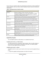
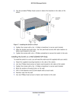
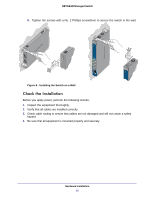
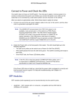
NETGEAR Managed Switch Connect to Power and Check the LEDs The switch does not have an On/Off switch. The only way to apply or remove power is to connect or disconnect the power cord. Before you connect the power cord, select an AC outlet that is not controlled by a wall switch (which can turn off power to the switch). After you select an appropriate outlet, follow these steps to apply AC power. 1. Connect one end of the AC power adapter cable to the rear of the switch, and the other end to a grounded 3-pronged AC outlet. Note: The GSM5212P can get power from PSE if AC power is not available. Just connect port 1 of the switch to a PSE (Power Sourcing Equipment) switch. The PSE device should support IEEE802.1at so that it can provide full power to GSM5212P for system operation. If the PSE device used does not support IEEE802.1at, the GSM5212P may not operate correctly. GSM7224P and GSM7212P switches support IEEE 802.1at on all ports. 2. Check the Power LED on the front panel of the switch. The LED should light up in the following sequence: • The LED turns yellow as the switch runs a Power-On Self-Test (POST). • If the switch passes the test, the LED turns green. The switch is working and ready to pass data. • If the POST fails, the Power LED blinks yellow. Note: If the PD LED on the front panel of GSM5212P blinks yellow, port 1 is connected to a IEEE802.1af PoE device. Check the PoE device specification to make sure it supports IEEE802.1at. If the Power LED does not light up, check that the power cable is plugged in correctly and that the power source is good. For help with troubleshooting, see Chapter 3.3, "Troubleshooting." SFP Modules SFP modules (sold separately) can be inserted directly into the switch's ports. • AGM731F - SFP module with LC connector, compatible with the IEEE 802.3z 1000Base-SX standard. Hardware Installation 16
-
 1
1 -
2
-
3
-
4
-
5
-
6
-
7
-
8
-
9
-
10
-
 11
11 -
 12
12 -
 13
13 -
 14
14 -
 15
15 -
 16
16 -
 17
17 -
 18
18 -
 19
19 -
 20
20 -
 21
21 -
22
-
23
-
24
-
25
-
26
-
27
-
28
 |
 |
