Netgear GSM7212P GSM5212P/GSM7212P/GSM7212F/GSM7224P Hardware Installation Gui - Page 4
Introduction, Front Panels and LEDs
 |
View all Netgear GSM7212P manuals
Add to My Manuals
Save this manual to your list of manuals |
Page 4 highlights
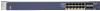
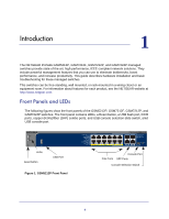
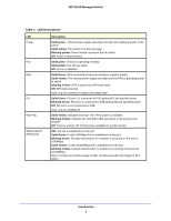
1. Introduction 1 The NETGEAR ProSafe GSM5212P, GSM7212F, GSM7212P, and GSM7224P managed switches provide state-of-the-art, high-performance, IEEE-compliant network solutions. They include powerful management features that you can use to eliminate bottlenecks, boost performance, and increase productivity. This guide describes hardware installation and basic troubleshooting for these managed switches. This switches can be free-standing, wall mounted, or rack-mounted in a wiring closet or an equipment room. For information about features for each product, see the NETGEAR website at http://www.netgear.com. Front Panels and LEDs The following figures show the front panels of the GSM5212P, GSM7212F, GSM7212P, and GSM7224P switches. The front panel contains LEDs, a Reset button, a USB flash port, RJ45 ports, copper (RJ45)/fiber (SFP) combo ports, and USB console selection slide switch, amd USB console port. LEDs Reset button USB Port Figure 1. GSM5212P Front Panel Console Port PoE Ports SFP Ports Console Selection Switch 4
-
 1
1 -
 2
2 -
 3
3 -
 4
4 -
 5
5 -
 6
6 -
 7
7 -
 8
8 -
 9
9 -
 10
10 -
11
-
12
-
13
-
14
-
15
-
16
-
17
-
18
-
19
-
20
-
21
-
22
-
23
-
24
-
25
-
26
-
27
-
28
 |
 |
