Netgear GSM7212P GSM5212P/GSM7212P/GSM7212F/GSM7224P Hardware Installation Gui - Page 6
Table 1., LED Descriptions
 |
View all Netgear GSM7212P manuals
Add to My Manuals
Save this manual to your list of manuals |
Page 6 highlights
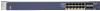
NETGEAR Managed Switch Table 1. LED Descriptions LED Power Fan RPS PD Max PoE SPD/Link/ACT (RJ45 port) Description Solid green: Internal power supply operating normally and supplying power to the switch Solid yellow: The system is in boot-up stage Blinking yellow: Power module is present but has failed Off: Power is disconnected. Solid green: The fan is operating normally Solid yellow: The fan has failed Off: No fan is detected Solid Green: RPS connected (Using internal power supply's power) Solid Yellow: The internal power supply has failed and the RPS is providing power to switch. Blinking Yellow: RPS is present but RPS has failed Off: RPS Disconnected Note: only for GSM7212F,GSM7212P,GSM7224P Solid Green: PD port 1 is connected to PSE getting 802.3at specified power Blinking Green: PD port 1 is connected to PSE getting 802.3af specified power Off: PD port 1 is not connected to PSE Note: only for GSM5212P Solid Yellow: Indicates less than 7W of PoE power is available Blinking Yellow: Indicates the PoE MAX LED was active in the previous two minutes Off: There is at least 7W of PoE power available for another device OFF: No link is established on the port Solid Green: A valid 1000Mbps link is established on the port Blinking Green: Packets transmission or reception is occurring on the port at 1000Mbps Solid Yellow: A valid 10/100Mbps link is established on the port Blinking Yellow: Packets transmission or reception is occurring on the port at 10/100Mbps Note: If combo port media change to fiber, the Ethernet LED will change to OFF status Introduction 6
-
 1
1 -
 2
2 -
 3
3 -
 4
4 -
 5
5 -
 6
6 -
 7
7 -
 8
8 -
 9
9 -
 10
10 -
 11
11 -
 12
12 -
13
-
14
-
15
-
16
-
17
-
18
-
19
-
20
-
21
-
22
-
23
-
24
-
25
-
26
-
27
-
28
 |
 |
