Netgear GSM7328Sv1 7000 Series Managed Switch Administration Guide for Softwar - Page 298
Removing a Unit from the Stack, Adding a Unit to an Operating Stack, no member, show switch
 |
View all Netgear GSM7328Sv1 manuals
Add to My Manuals
Save this manual to your list of manuals |
Page 298 highlights
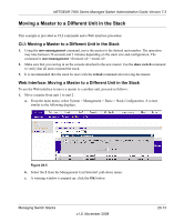
NETGEAR 7000 Series Managed Switch Administration Guide Version 7.3 6. Power on a second unit, making sure it is adjacent (next physical unit in the stack) to the unit already powered up. This will insure the second unit comes up as a member of the stack, and not a "Master" of a separate stack. 7. Monitor the master unit to see that the second unit joins the stack. Use the "show switch" command to determine when the unit joins the stack. It will be assigned a unit number (unit #2, if it has the default configuration). 8. Renumber this stack unit, if desired. See section "Renumber Stack Members" on recommendations for renumbering stack members. 9. Repeat steps 6 through 8 to add additional members to the stack. Always power on a unit adjacent to the units already in the stack. Removing a Unit from the Stack 1. Make sure the redundant stack connection is in place and functional. All stack members should be connected in a logical ring. 2. Power down the unit to be removed. 3. Disconnect stack cables. 4. If unit is not to be replaced, reconnect the stack cable from the stack member above to the stack member below the unit being removed. 5. Remove unit from the rack. 6. If desired, remove the unit from the configuration by issuing the command: no member Adding a Unit to an Operating Stack 1. Make sure the redundant stack connection is in place and functional. All stack members should be connected in a logical ring. 2. Preconfigure the new unit, if desired. 3. Install new unit in the rack. (Assumes installation below the bottom-most unit, or above the top-most unit). 4. Disconnect the redundant stack cable that connects the last unit in the stack back up to the first unit in the stack at the position in the ring where the new unit is to be inserted. 5. Connect this cable to the new unit, following the established order of "stack up" to "stack down" connections 6. Power up the new unit. Verify, by monitoring the master unit console port, that the new unit successfully joins the stack by issuing the show switch command. The new unit should always join as a "member" (never as master; the existing master of the stack should not change). 7. If the code version of the newly added member is not the same as the existing stack, update the code as described in section "Upgrading Firmware". 20-10 v1.0, November 2008 Managing Switch Stacks
-
 1
1 -
2
-
3
-
4
-
5
-
6
-
7
-
8
-
9
-
10
-
11
-
12
-
13
-
14
-
15
-
16
-
17
-
18
-
19
-
20
-
21
-
22
-
23
-
24
-
25
-
26
-
27
-
28
-
29
-
30
-
31
-
32
-
33
-
34
-
35
-
36
-
37
-
38
-
39
-
40
-
41
-
42
-
43
-
44
-
45
-
46
-
47
-
48
-
49
-
50
-
51
-
52
-
53
-
54
-
55
-
56
-
57
-
58
-
59
-
60
-
61
-
62
-
63
-
64
-
65
-
66
-
67
-
68
-
69
-
70
-
71
-
72
-
73
-
74
-
75
-
76
-
77
-
78
-
79
-
80
-
81
-
82
-
83
-
84
-
85
-
86
-
87
-
88
-
89
-
90
-
91
-
92
-
93
-
94
-
95
-
96
-
97
-
98
-
99
-
100
-
101
-
102
-
103
-
104
-
105
-
106
-
107
-
108
-
109
-
110
-
111
-
112
-
113
-
114
-
115
-
116
-
117
-
118
-
119
-
120
-
121
-
122
-
123
-
124
-
125
-
126
-
127
-
128
-
129
-
130
-
131
-
132
-
133
-
134
-
135
-
136
-
137
-
138
-
139
-
140
-
141
-
142
-
143
-
144
-
145
-
146
-
147
-
148
-
149
-
150
-
151
-
152
-
153
-
154
-
155
-
156
-
157
-
158
-
159
-
160
-
161
-
162
-
163
-
164
-
165
-
166
-
167
-
168
-
169
-
170
-
171
-
172
-
173
-
174
-
175
-
176
-
177
-
178
-
179
-
180
-
181
-
182
-
183
-
184
-
185
-
186
-
187
-
188
-
189
-
190
-
191
-
192
-
193
-
194
-
195
-
196
-
197
-
198
-
199
-
200
-
201
-
202
-
203
-
204
-
205
-
206
-
207
-
208
-
209
-
210
-
211
-
212
-
213
-
214
-
215
-
216
-
217
-
218
-
219
-
220
-
221
-
222
-
223
-
224
-
225
-
226
-
227
-
228
-
229
-
230
-
231
-
232
-
233
-
234
-
235
-
236
-
237
-
238
-
239
-
240
-
241
-
242
-
243
-
244
-
245
-
246
-
247
-
248
-
249
-
250
-
251
-
252
-
253
-
254
-
255
-
256
-
257
-
258
-
259
-
260
-
261
-
262
-
263
-
264
-
265
-
266
-
267
-
268
-
269
-
270
-
271
-
272
-
273
-
274
-
275
-
276
-
277
-
278
-
279
-
280
-
281
-
282
-
283
-
284
-
285
-
286
-
287
-
288
-
289
-
290
-
291
-
292
-
 293
293 -
 294
294 -
 295
295 -
 296
296 -
 297
297 -
 298
298 -
 299
299 -
 300
300 -
 301
301 -
 302
302 -
 303
303 -
304
-
305
-
306
-
307
-
308
-
309
-
310
-
311
-
312
-
313
-
314
-
315
-
316
-
317
-
318
-
319
-
320
-
321
-
322
-
323
-
324
-
325
-
326
-
327
-
328
-
329
-
330
-
331
-
332
-
333
-
334
-
335
-
336
-
337
-
338
-
339
-
340
-
341
-
342
-
343
-
344
 |
 |
