Netgear M5300-28G3 Hardware Installation Guide - Page 14
Check the Installation, Connect to Power and Check the LEDs, SFP+ and SFP Modules
 |
View all Netgear M5300-28G3 manuals
Add to My Manuals
Save this manual to your list of manuals |
Page 14 highlights
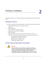
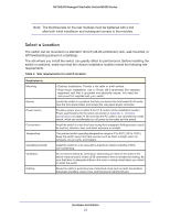
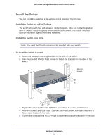
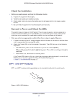
NETGEAR Managed Stackable Switch M5300 Series Check the Installation Before you apply power, perform the following checks: 1. Inspect the equipment thoroughly. 2. Verify that all cables are installed correctly. 3. Check cable routing to ensure that cables are not damaged and do not create a safety hazard. 4. Be sure that all equipment is mounted properly and securely. Connect to Power and Check the LEDs The switch does not have an On/Off switch. The only way to apply or remove power is to connect or disconnect the power cord. Before you connect the power cord, select an AC outlet that is not controlled by a wall switch (which can turn off power to the switch). After you select an appropriate outlet, follow these steps to apply AC power: 1. Connect one end of the AC power adapter cable to the rear of the switch, and the other end to a grounded three-prong AC outlet. 2. Check the Power LED on the front panel of the switch. The LED lights up in the following sequence: • The LED turns yellow as the switch runs a power-on self-test (POST). • If the switch passes the test, the LED turns green. The switch is working and ready to pass data. • If the POST fails, the Power LED blinks yellow. If the Power LED does not light up, check that the power cable is plugged in correctly and that the power source is good. For help with troubleshooting, see Chapter 3,Troubleshooting on page 22." SFP+ and SFP Modules SFP+ and SFP modules (sold separately) can be inserted directly into the switch ports. Figure 4. SFP+ SFP Modules Hardware Installation 14
-
 1
1 -
2
-
3
-
4
-
5
-
6
-
7
-
8
-
 9
9 -
 10
10 -
 11
11 -
 12
12 -
 13
13 -
 14
14 -
 15
15 -
 16
16 -
 17
17 -
 18
18 -
 19
19 -
20
-
21
-
22
-
23
-
24
-
25
-
26
-
27
-
28
-
29
-
30
-
31
-
32
 |
 |