Netgear M5300-28G3 Hardware Installation Guide - Page 19
Connect a Redundant Power Supply, Connect Equipment to the Switch, RJ-45 Ports
 |
View all Netgear M5300-28G3 manuals
Add to My Manuals
Save this manual to your list of manuals |
Page 19 highlights
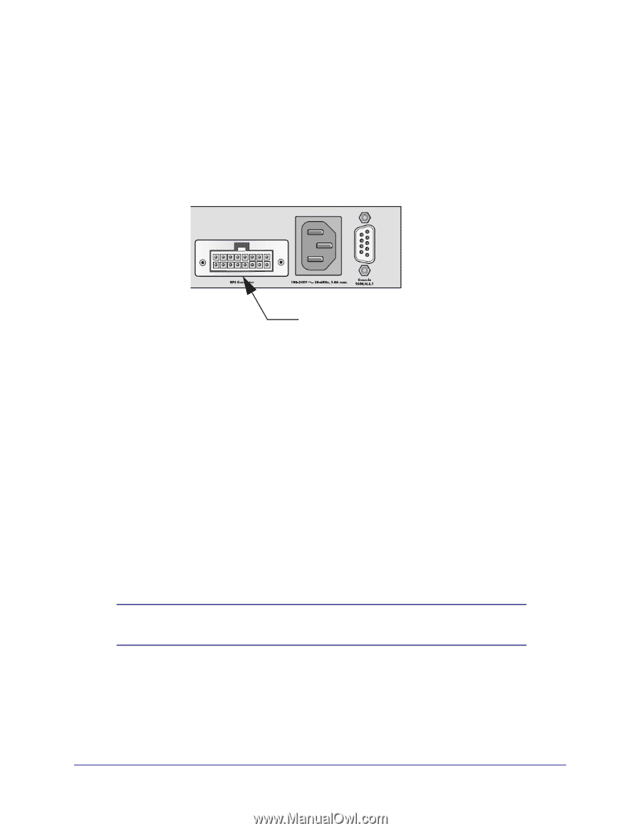
NETGEAR Managed Stackable Switch M5300 Series 3. Loosen the two captive screws on the power module. 4. Remove the power module from the power module slot by pulling on the extraction handle. Connect a Redundant Power Supply Each switch has a redundant power supply (RPS) connector at the rear of the switch next to the power receptacle. Redundant power supply jack You can connect an external UL-listed DC-to-DC power supply unit to the switch to provide redundant power in case the primary power supply fails. To connect an (RPS) unit to the switch, first turn off the switch. When the power is off, you can remove the cover plate and connect the RPS unit to the switch. After all connections are completed, apply power to the switch. Connect Equipment to the Switch You can connect devices, a Gigabit Ethernet module, and/or a console to the switch. RJ-45 Ports The switch uses Auto Uplink™ technology, which enables you to attach devices using either straight-through or crossover cables. Use a Category 5 (Cat5) unshielded twisted-pair (UTP) cable terminated with an RJ-45 connector. Note: Ethernet specifications limit the cable length between the switch and the attached device to 328 feet (100 meters). Hardware Installation 19
-
 1
1 -
2
-
3
-
4
-
5
-
6
-
7
-
8
-
9
-
10
-
11
-
12
-
13
-
 14
14 -
 15
15 -
 16
16 -
 17
17 -
 18
18 -
 19
19 -
 20
20 -
 21
21 -
 22
22 -
 23
23 -
 24
24 -
25
-
26
-
27
-
28
-
29
-
30
-
31
-
32
 |
 |