Netgear M5300-28G3 Hardware Installation Guide - Page 17
Stacking Using IO Module on the Rear Panel, To set up a stack
 |
View all Netgear M5300-28G3 manuals
Add to My Manuals
Save this manual to your list of manuals |
Page 17 highlights
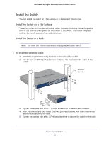
NETGEAR Managed Stackable Switch M5300 Series 3. Connect each switch to the next in a cascade to build the backplane of the stack. Finally, connect the last switch in the stack to the first switch to close the ring and provide redundancy and resiliency to the stack. The switches automatically select the master switch in the stack. 4. To use the console and command-line interface (CLI), use a serial cable to connect the console to the master switch. This single console connection lets you manage all the switches in the stack. For information about working with the CLI, see the Command Line Interface manual on the resource CD that shipped with your product. Stacking Using IO Module on the Rear Panel You can connect up to eight switches to form a stack with a single management IP address. The switches automatically select a master unit. Once the master is selected, you can use its console to manage all the switches in the stack. Two of the I/O module slots can be used for stacking, while the remaining two I/O module bays can be used for 10-Gigabit Ethernet uplinks. To set up a stack: 1. Install up to two 24-Gigabit Stackable Modules (AX742) into the high-speed I/O module bays at the front or the rear of each switch. 2. Connect the provided stacking cable between a pair of AX742 modules in each switch within a stack. AX742 stacking cable 3. Connect each switch to the next in a cascade to build the backplane of the stack. Finally, connect the last switch in the stack to the first switch, to close the ring and provide redundancy and resiliency to the stack. The switches automatically select the master switch in the stack. 4. To use the console and Command Line Interface (CLI), use a serial cable to connect the console to the master switch. This single console connection lets you manage all the switches in the stack. Hardware Installation 17
-
 1
1 -
2
-
3
-
4
-
5
-
6
-
7
-
8
-
9
-
10
-
11
-
 12
12 -
 13
13 -
 14
14 -
 15
15 -
 16
16 -
 17
17 -
 18
18 -
 19
19 -
 20
20 -
 21
21 -
 22
22 -
23
-
24
-
25
-
26
-
27
-
28
-
29
-
30
-
31
-
32
 |
 |