Netgear M5300-28G3 Hardware Installation Guide - Page 7
M5300 Series Rear Panel, M5300 Series rear panel, Table 1.
 |
View all Netgear M5300-28G3 manuals
Add to My Manuals
Save this manual to your list of manuals |
Page 7 highlights
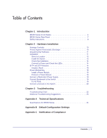
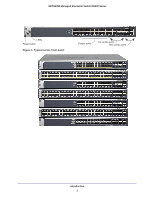
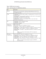
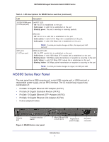
NETGEAR Managed Stackable Switch M5300 Series Table 1. LED descriptions for M5300 Series switches (continued) LED Description 10/100/1000M ports (2 LEDs per port) Link/ACT LED: • Off: No link is established on the port. • Solid green: A valid link is established on the port. • Blinking green: The port is sending or receiving packets. SFP ports (1 LED per port) SPD LED: • Off: No link or a valid link is established on the port. • Solid yellow: A valid 10/100 Mbps link is established on the port. • Solid green: A valid 1000 Mbps link is established on the port. Note: If combo port media changes to fiber, the copper port LED turns off. SPD/Link/ACT LED: • Off: No SFP module link is established on the port. • Solid Green: A valid 1000 Mbps SFP module link is established on the port. • Blinking Green: 1000 Mbps packet transmission or reception is occurring on the port. • Solid Yellow: A valid 100 Mbps SFP module link is established on the port. • Blinking Yellow: 100 Mbps packet transmission or reception is occurring on the port. Note: If combo port media changes to copper, the SFP port LED turns off. M5300 Series Rear Panel The rear panel has a DB9 console port, a mini-USB console port, a USB host port, a replaceable power supply, and an RPS interface. The IO module bays support any combination of: • ProSafe 10 Gigabit Ethernet XFP Adapter (AX741) • ProSafe 24 Gigabit Stackable Module (AX742) • ProSafe 10 Gigabit Ethernet SFP+ Adapter (AX743) • ProSafe 10 Gigabit Ethernet CX4 Adapter (AX744) • Future adapter/module. Console port Console selection switch Figure 3. M5300 Series rear panel Mini-USB and USB console ports Replaceable power supply AC power connector Introduction 7
-
 1
1 -
 2
2 -
 3
3 -
 4
4 -
 5
5 -
 6
6 -
 7
7 -
 8
8 -
 9
9 -
 10
10 -
 11
11 -
 12
12 -
13
-
14
-
15
-
16
-
17
-
18
-
19
-
20
-
21
-
22
-
23
-
24
-
25
-
26
-
27
-
28
-
29
-
30
-
31
-
32
 |
 |