Nintendo GAMECUBE Instruction Booklet - Page 4
Top View, Front View, Back View - memory card
 |
UPC - 045496940027
View all Nintendo GAMECUBE manuals
Add to My Manuals
Save this manual to your list of manuals |
Page 4 highlights
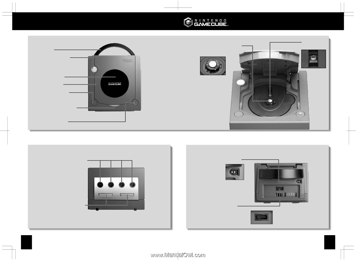
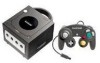
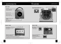
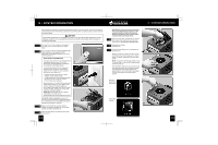
1• COMPONENTS TOP VIEW Handle Power Button Turns power ON or OFF Name Plate Disc Cover Reset Button Power Indicator Light Lights when power is on Open Button Opens disc cover FRONT VIEW Controller Sockets For connection of Nintendo GameCube controllers and accessories 12 34 Disc Release Button Press to release Game Disc BACK VIEW DC Input Connector (DC 12V IN) Connects the DC Jack of the AC Adapter Memory Card Slots (SLOT A and SLOT B) SLOT A SLOT B For connection of Nintendo GameCube Memory Cards (Sold separately, see back cover for purchasing information.) See pages 18-20 for more information on using Memory Cards and the game instruction booklet for specific information on how to save game information to a memory card. 2 Analog AV Output (ANALOG AV OUT) (Multi Out Connector) Connects the Stereo Audio/Video Cable See pages 8-10 1• COMPONENTS Lens Do not touch 3
-
 1
1 -
 2
2 -
 3
3 -
 4
4 -
 5
5 -
 6
6 -
 7
7 -
 8
8 -
 9
9 -
 10
10 -
11
-
12
-
13
-
14
-
15
-
16
 |
 |