Nokia IP390 Installation Guide - Page 55
Configuring and Activating Interfaces, Monitoring Network Interface Cards - commands
 |
View all Nokia IP390 manuals
Add to My Manuals
Save this manual to your list of manuals |
Page 55 highlights
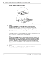
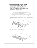
Configuring and Activating Interfaces 11. Tighten the retaining screws that hold the chassis tray assembly. Chassis tray assembly retaining screws IP390 00525 Configuring and Activating Interfaces The IP390 appliance automatically detects any new NIC when the appliance is restarted. Use Network Voyager to configure and activate the logical and physical interfaces on the NIC. For information about how to access Network Voyager and the related reference materials, see "Using Nokia Network Voyager" on page 33. Monitoring Network Interface Cards You can asses the general operating condition of the NICs in your appliance by looking at the LED status indicators on the NICs. The status indicators for each NIC are explained in the NIC reference chapter. For status indicator information for the built-in Gigabit Ethernet ports, see "Built-In Gigabit Ethernet Ports" on page 18. For status indicator information for the four-port Ethernet NIC, see "Four-Port 10/100 Mbps Ethernet Network Interface Card" on page 37. For status indicator information for the two-port copper Gigabit Ethernet NIC, see "Two-Port Copper Gigabit Ethernet Network Interface Card" on page 40. For status indicator information for the two-port fiber-optic Gigabit Ethernet NIC, see "TwoPort Fiber-Optic Gigabit Ethernet Network Interface Card" on page 42. For status indicator information for the four-port T1 NIC, see "Four-Port T1 Network Interface Card" on page 45. Use Network Voyager to access detailed port information. For information about accessing Network Voyager, see "Using Nokia Network Voyager" on page 33. You can also use the Nokia IPSO tcpdump command to examine the track on a specific port. IP390 Security Platform Installation Guide 55
-
 1
1 -
2
-
3
-
4
-
5
-
6
-
7
-
8
-
9
-
10
-
11
-
12
-
13
-
14
-
15
-
16
-
17
-
18
-
19
-
20
-
21
-
22
-
23
-
24
-
25
-
26
-
27
-
28
-
29
-
30
-
31
-
32
-
33
-
34
-
35
-
36
-
37
-
38
-
39
-
40
-
41
-
42
-
43
-
44
-
45
-
46
-
47
-
48
-
49
-
 50
50 -
 51
51 -
 52
52 -
 53
53 -
 54
54 -
 55
55 -
 56
56 -
 57
57 -
 58
58 -
 59
59 -
 60
60 -
61
-
62
-
63
-
64
-
65
-
66
-
67
-
68
-
69
-
70
-
71
-
72
-
73
-
74
-
75
-
76
-
77
-
78
-
79
-
80
-
81
-
82
-
83
-
84
-
85
-
86
-
87
-
88
-
89
-
90
-
91
-
92
-
93
-
94
-
95
-
96
-
97
 |
 |
