Onkyo TX-SV525 Owner Manual - Page 15
bearing, connected, input, there, loudspeakers, another, should, impedance, cables.
 |
View all Onkyo TX-SV525 manuals
Add to My Manuals
Save this manual to your list of manuals |
Page 15 highlights
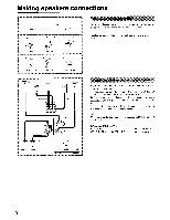
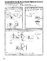
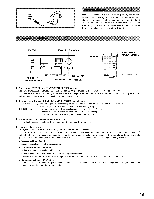
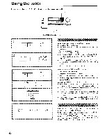
2. ONKYO RTC system (Models other than U.S.A and Canadian models) y MT When using only the HR-10 (optional) to control this unit in the main room from another room, connect them as shown below. In this case, both the ONKYO CD player and the cassette tape t deck bearing the RI mark and connected to this unit can be controlled. REMOTE Loudspeaker set MAIN Loudspeakers O 0 0 TX-SV525(IR Main room O HR 10 O 0 O0 0 MAIN Remote control 0 Loudspeaker Another room 11•1111•1111111, To enable remote control operation when this unit is mounted in a rack which will not permit infrared beams to pass, mount the HR-10 outside the rack so that the signals can be picked up. If all components bear the RI mark, connect a cable from the HR-10 to the ITRK input on this unit, and from there connect IR! cables to the other components (sec page 9). If the other components can receive infrared remote control signals, but do not have the RI mark, mount an HE-50(AC) inside the cabinet so that signals from it will reach the sensors in all components, and connect it to the HR-10 with an cable. Remote control Hanoi 000001 HR-10 HE-50(AC) to REMOTE speakers Bottom of HR-10) RO ',PEA EPS EMOTE Green IN terminal 0 ,, I. To REMOTE loudspeakers set Rear panel of the TX-SV525fIR CASSETTE TAPE DECK COMPACT DISC PLAYER , x44, T • ,,- rtt), A connection example using the HR-10 (optional) and HE-50 (AC) (optional) to control components in the main room from another room is shown below. If all the components can not be controlled by the HE-50 (AC) alone because they are installed at various places in the main room, use a Remote Emitter head HE-10 (optional). This also allows you to control components that are not ONKYO, or do not have an RI mark, as long as they can be controlled by infrared remote control. When using an HE-50(AC), the HE-50(AC) or HE- IC should also face this unit. Note on multiple room cables Any remote sensors and emitters (HR-10, HE-50(AC), HE-10) should be connected with low capacitance shielded 2-wire coaxial cables with 1/8" (3.5 mm diameter) mini-plug connectors. Maximum cable length is determined by the characteristics of the particular cables used but up to approximately 164' (50 m) lengths are generally practical. Refer to the instruction manual which comes with the HR-10 when making these connections. Sets of loudspeakers in another room should be connected to this unit in the main room with low impedance cables. MAIN Loudspeaker MAIN Loudspeaker REMOTE Loudspeaker HE-10 AC adaptor HE-50 (AC) O 53 Main room O HR 10 REMOTE ) Loudspeaker JTX-SV525/R Another room Remote control to AC adaptor Vl ;G'2reen terminal I 0 IV OOUT O O omnrO Bottom or HE-50 (AC) j to HE 10 o REMOTE speakers set H'n Bottom of HR-10 Rea panel of the TX SV525/R NOTES: • Always unplug the AC power cords for this unit and HE-50 (AC) when connecting the ITRK. • Insert the 1TR mini-plug into the green terminal on the rear panel of this unit. 15
-
 1
1 -
2
-
3
-
4
-
5
-
6
-
7
-
8
-
9
-
 10
10 -
 11
11 -
 12
12 -
 13
13 -
 14
14 -
 15
15 -
 16
16 -
 17
17 -
 18
18 -
 19
19 -
 20
20 -
21
-
22
-
23
-
24
-
25
-
26
-
27
-
28
-
29
-
30
-
31
-
32
 |
 |
