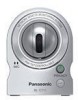
Panasonic BL-C111A Service Manual - Page 14
PAN Control Block, TILT Motor Control Block, LED Control Block - mount
 |
UPC - 037988845149
View all Panasonic BL-C111A manuals
Add to My Manuals
Save this manual to your list of manuals |
Page 14 highlights
BL-C111A /BL-C131A 4.1.7. PAN Control Block A pan motor operates, when CPU (IC101) on a Main Board controls the Motor Driver IC (IC402) on the same board. A Constant Voltage Bipolar Drive System is employed. The Voltage of Motor Power (VM) is 3.3V. ø15 Stepping Motors are employed. 4.1.8. TILT Motor Control Block A Tilt motor operates, when CPU (IC101) on a main board controls the motor driver IC (IC402) on the same board. A Constant Voltage Bipolar Drive System is employed. The Voltage of Motor Power (VM) is 3.3V. ø15 Stepping Motors are employed. 4.1.9. LED Control Block LED is controlled by CPU which is mounted on Main Board. Control data is input into LED Control Circuit which is mounted on Sub Board. (Three color LED is employed.) LED_R L L H H LED_G L H L H Color of LED OFF Green Red Orange 14
-
 1
1 -
2
-
3
-
4
-
5
-
6
-
7
-
8
-
 9
9 -
 10
10 -
 11
11 -
 12
12 -
 13
13 -
 14
14 -
 15
15 -
 16
16 -
 17
17 -
 18
18 -
 19
19 -
20
-
21
-
22
-
23
-
24
-
25
-
26
-
27
-
28
-
29
-
30
-
31
-
32
-
33
-
34
-
35
-
36
-
37
-
38
-
39
-
40
-
41
-
42
-
43
-
44
-
45
-
46
-
47
-
48
-
49
-
50
-
51
-
52
-
53
-
54
-
55
-
56
-
57
-
58
-
59
-
60
-
61
-
62
-
63
-
64
-
65
-
66
-
67
-
68
-
69
-
70
-
71
-
72
-
73
-
74
-
75
-
76
-
77
-
78
-
79
-
80
-
81
-
82
-
83
 |
 |
