Panasonic BL-C111A Service Manual - Page 16
RF BlockC131A only - mac
 |
UPC - 037988845149
View all Panasonic BL-C111A manuals
Add to My Manuals
Save this manual to your list of manuals |
Page 16 highlights
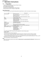
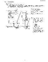
BL-C111A /BL-C131A 4.2. RF Block(C131A only) • Antenna • Receiver The receiving signal from the antenna is input to the RFIC (IC601) after being passed through the Antenna Switch (IC502) and amplified at LNA (Low Noise Amp).The RFIC (IC601) incorporates the LNA (Low Noise Amp), the Mixer for Frequency Converter and the Synthesizer generating the Receiving Local Signal. At the RFIC (IC601), the input signal is separated into the baseband signals of the In-Phase(RxI) and Quadrature (RxQ) to output. The baseband signal is input to the CPU&MAC/BB/RFIC(IC601) and, after A/D conversion, the data are regenerated. • Transmitter The Data Frame (Data Packet) generated at the built-in MAC Part by the CPU&MAC/BB/RFIC (IC601) is converted to the RF Signal of the transmitting frequency band. After processing including impedance conversion, level adjustment and control of the unnecessary frequency component, it is sent from the antenna through the Antenna Switch (IC502). The RF Signal from the Power Amp (IC501) is fed back to the RFIC (IC601) after level detection. The gain is adjusted in the RFIC (IC601) for a constant transmitter output level. 16
-
 1
1 -
2
-
3
-
4
-
5
-
6
-
7
-
8
-
9
-
10
-
 11
11 -
 12
12 -
 13
13 -
 14
14 -
 15
15 -
 16
16 -
 17
17 -
 18
18 -
 19
19 -
 20
20 -
 21
21 -
22
-
23
-
24
-
25
-
26
-
27
-
28
-
29
-
30
-
31
-
32
-
33
-
34
-
35
-
36
-
37
-
38
-
39
-
40
-
41
-
42
-
43
-
44
-
45
-
46
-
47
-
48
-
49
-
50
-
51
-
52
-
53
-
54
-
55
-
56
-
57
-
58
-
59
-
60
-
61
-
62
-
63
-
64
-
65
-
66
-
67
-
68
-
69
-
70
-
71
-
72
-
73
-
74
-
75
-
76
-
77
-
78
-
79
-
80
-
81
-
82
-
83
 |
 |
