Panasonic DMR-E65S Dvd Recorder - Page 8
Connecting a cable TV box, Should I use the AUDIO/VIDEO OUT terminal or, the RF OUT terminal? - manual
 |
UPC - 037988407545
View all Panasonic DMR-E65S manuals
Add to My Manuals
Save this manual to your list of manuals |
Page 8 highlights
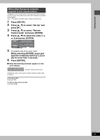
Getting started STEP 1 Connection Connecting a cable TV box ≥You need to subscribe to a cable TV service to enjoy viewing their programming. ≥Consult your service provider regarding appropriate cable TV box. ≥If you receive your programming solely from a satellite service, the program guide in this unit will not receive program listings or channel information. Without this information, program-based recordings cannot be made. However, recordings can still be set manually. A to Q are indexes for Spanish Quick Reference. A Television AUDIO IN R L VIDEO IN S VIDEO IN VHF/UHF RF IN B This unit C Audio/video cable§ D 75 ≠ coaxial cable§ RF IN IN1 OUT1 OUT2 G-LINK R - AUDIO - L VIDEO S-VIDEO Y PB PR R - AUDIO - L VIDEO S-VIDEO (L1) E IR Blaster Insert the IR Blaster jack into the G-LINK terminal. The cable TV box is controlled by an IR signal transmitted through the IR Blaster. When selecting channels on this unit, the corresponding channels on the cable TV box also change accordingly. ≥Only use the included IR Blaster. OPTICAL IN3 R - AUDIO - L VIDEO S-VIDEO COMPONENT VIDEO OUT (480P/480I) DIGITAL AUDIO OUT (PCM/BITSTREAM) R - AUDIO - L VIDEO S-VIDEO (L3) RF OUT VHF/UHF G Red White Yellow H Connect to either this F Use IN3 (L3) [not IN1 (L1)]. unit's RF IN terminal or IN3 (L3) terminal. C Audio/video cable D 75 ≠ coaxial cable I S-Video cable G Red White Yellow OUT IN J Setting the IR Blaster ➡ below R L AUDIO VIDEO S-VIDEO RF K Cable TV box L From antenna or cable TV jack § For more information on connections (➡ page 7) ∫ Should I use the AUDIO/VIDEO OUT terminal or the RF OUT terminal? If your cable TV box has both AUDIO/VIDEO OUT terminals and RF OUT terminals, we recommend connecting the AUDIO/VIDEO OUT terminal with the unit's IN3 (L3) terminal. Using this connection provides better picture quality. ≥The S-VIDEO terminal achieves a more vivid picture than the VIDEO terminal. Setting the IR Blaster Place the IR Blaster in front of the signal sensor of the cable TV box. M Read the cable TV box operating instructions regarding positioning of the signal sensor. N If necessary, use the double sided adhesive tape (included) to secure the IR Blaster to a flat surface. O e.g. Television stand surface RQT7303 8 P Cable TV box Q If you peel off the adhesive tape, the surface may become damaged. Once you have confirmed the cable TV box is operating correctly, secure it by attaching the adhesive tape.
-
 1
1 -
2
-
 3
3 -
 4
4 -
 5
5 -
 6
6 -
 7
7 -
 8
8 -
 9
9 -
 10
10 -
 11
11 -
 12
12 -
 13
13 -
14
-
15
-
16
-
17
-
18
-
19
-
20
-
21
-
22
-
23
-
24
-
25
-
26
-
27
-
28
-
29
-
30
-
31
-
32
-
33
-
34
-
35
-
36
-
37
-
38
-
39
-
40
-
41
-
42
-
43
-
44
-
45
-
46
-
47
-
48
-
49
-
50
-
51
-
52
-
53
-
54
-
55
-
56
-
57
-
58
-
59
-
60
 |
 |
