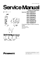
Panasonic KX-TG9341T Service Manual - Page 3

Table Of Contents - user guide

Page 3 highlights

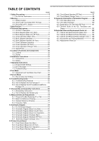
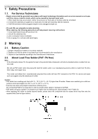
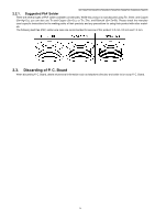
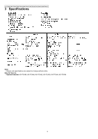
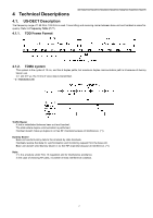
TABLE OF CONTENTS KX-TG9341T/KX-TG9342T/KX-TG9343S/KX-TG9343T/KX-TG9344T/KX-TGA931S/KX-TGA931T PAGE 1 Safety Precautions 4 1.1. For Service Technicians 4 2 Warning 4 2.1. Battery Caution 4 2.2. About Lead Free Solder (PbF: Pb free 4 2.3. Discarding of P. C. Board 5 3 Specifications 6 4 Technical Descriptions 7 4.1. US-DECT Description 7 4.2. Block Diagram (Base Unit_Main 9 4.3. Block Diagram (Base Unit_RF Part 10 4.4. Circuit Operation (Base Unit 11 4.5. Block Diagram (Handset 20 4.6. Block Diagram (Handset_RF Part 21 4.7. Circuit Operation (Handset 22 4.8. Circuit Operation (RF Part 26 4.9. Circuit Operation (Charger Unit 27 4.10. Signal Route 28 5 Location of Controls and Components 30 5.1. Controls 30 5.2. Display 30 6 Installation Instructions 31 6.1. Connections 31 6.2. Battery 31 7 Operating Instructions 33 7.1. Programmable Settings 33 7.2. Error Messages 36 7.3. Troubleshooting 37 8 Test Mode 41 8.1. Adjustment and Test Mode Flow Chart 41 9 Service Mode 48 9.1. How to Clear User Setting 48 10 Troubleshooting Guide 50 10.1. Troubleshooting Flowchart 50 10.2. How to Replace the Flat Package IC 63 10.3. How to Replace the LLP (Leadless Leadframe Package) IC 65 11 Disassembly and Assembly Instructions 68 11.1. Disassembly Instructions 68 11.2. How to Replace the Handset LCD 72 12 Measurements and Adjustments 74 12.1. Things to Do after Replacing IC or X'tal 74 12.2. Base Unit Reference Drawing 75 12.3. Handset Reference Drawing 76 12.4. Frequency Table 77 13 Schematic Diagram 79 13.1. For Schematic Diagram 79 13.2. Schematic Diagram (Base Unit_Main 80 13.3. Schematic Diagram (Base Unit_RF Part) ----------82 13.4. Schematic Diagram (Base Unit_Operation) -------83 13.5. Schematic Diagram (Handset_Main 84 13.6. Schematic Diagram (Handset_RF Part 86 13.7. Schematic Diagram (Charger Unit 87 14 Printed Circuit Board 89 14.1. Circuit Board (Base Unit_Main 89 14.2. Circuit Board (Base Unit_RF Part 91 14.3. Circuit Board (Base Unit_Operation 93 14.4. Circuit Board (Handset_Main 95 PAGE 14.5. Circuit Board (Handset_RF Part 97 14.6. Circuit Board (Charger Unit 98 15 Appendix Information of Schematic Diagram --------- 99 15.1. CPU Data (Base Unit 99 15.2. CPU Data (Handset 100 15.3. Explanation of IC Terminals (RF Part 101 15.4. Terminal Guide of the ICs, Transistors and Diodes 102 16 Exploded View and Replacement Parts List --------- 103 16.1. Cabinet and Electrical Parts (Base Unit) --------- 103 16.2. Cabinet and Electrical Parts (Handset 104 16.3. Cabinet and Electrical Parts (Charger Unit) ----- 105 16.4. Accessories and Packing Materials 106 16.5. Replacement Parts List 110 3

  • 1
  • 2
  • 3
  • 4
  • 5
  • 6
  • 7
  • 8
  • 9
  • 10
  • 11
  • 12
  • 13
  • 14
  • 15
  • 16
  • 17
  • 18
  • 19
  • 20
  • 21
  • 22
  • 23
  • 24
  • 25
  • 26
  • 27
  • 28
  • 29
  • 30
  • 31
  • 32
  • 33
  • 34
  • 35
  • 36
  • 37
  • 38
  • 39
  • 40
  • 41
  • 42
  • 43
  • 44
  • 45
  • 46
  • 47
  • 48
  • 49
  • 50
  • 51
  • 52
  • 53
  • 54
  • 55
  • 56
  • 57
  • 58
  • 59
  • 60
  • 61
  • 62
  • 63
  • 64
  • 65
  • 66
  • 67
  • 68
  • 69
  • 70
  • 71
  • 72
  • 73
  • 74
  • 75
  • 76
  • 77
  • 78
  • 79
  • 80
  • 81
  • 82
  • 83
  • 84
  • 85
  • 86
  • 87
  • 88
  • 89
  • 90
  • 91
  • 92
  • 93
  • 94
  • 95
  • 96
  • 97
  • 98
  • 99
  • 100
  • 101
  • 102
  • 103
  • 104
  • 105
  • 106
  • 107
  • 108
  • 109
  • 110
  • 111
  • 112
  • 113
  • 114
  • 115

3
KX-TG9341T/KX-TG9342T/KX-TG9343S/KX-TG9343T/KX-TG9344T/KX-TGA931S/KX-TGA931T
TABLE OF CONTENTS
PAGE
PAGE
1 Safety Precautions
-----------------------------------------------
4
1.1. For Service Technicians --------------------------------- 4
2 Warning
--------------------------------------------------------------
4
2.1. Battery Caution--------------------------------------------- 4
2.2. About Lead Free Solder (PbF: Pb free)-------------- 4
2.3. Discarding of P. C. Board-------------------------------- 5
3 Specifications
-----------------------------------------------------
6
4 Technical Descriptions
-----------------------------------------
7
4.1. US-DECT Description ------------------------------------ 7
4.2. Block Diagram (Base Unit_Main)---------------------- 9
4.3. Block Diagram (Base Unit_RF Part)-----------------10
4.4. Circuit Operation (Base Unit)--------------------------11
4.5. Block Diagram (Handset)-------------------------------20
4.6. Block Diagram (Handset_RF Part)-------------------21
4.7. Circuit Operation (Handset)----------------------------22
4.8. Circuit Operation (RF Part)-----------------------------26
4.9. Circuit Operation (Charger Unit)----------------------27
4.10. Signal Route -----------------------------------------------28
5 Location of Controls and Components
------------------
30
5.1. Controls -----------------------------------------------------30
5.2. Display ------------------------------------------------------30
6 Installation Instructions
---------------------------------------
31
6.1. Connections------------------------------------------------31
6.2. Battery-------------------------------------------------------31
7 Operating Instructions
-----------------------------------------
33
7.1. Programmable Settings---------------------------------33
7.2. Error Messages -------------------------------------------36
7.3. Troubleshooting-------------------------------------------37
8 Test Mode
----------------------------------------------------------
41
8.1. Adjustment and Test Mode Flow Chart -------------41
9 Service Mode
-----------------------------------------------------
48
9.1. How to Clear User Setting------------------------------48
10 Troubleshooting Guide
----------------------------------------
50
10.1. Troubleshooting Flowchart -----------------------------50
10.2. How to Replace the Flat Package IC----------------63
10.3. How to Replace the LLP (Leadless Leadframe
Package) IC------------------------------------------------65
11 Disassembly and Assembly Instructions
---------------
68
11.1. Disassembly Instructions -------------------------------68
11.2. How to Replace the Handset LCD -------------------72
12 Measurements and Adjustments
---------------------------
74
12.1. Things to Do after Replacing IC or X’tal ------------74
12.2. Base Unit Reference Drawing-------------------------75
12.3. Handset Reference Drawing---------------------------76
12.4. Frequency Table------------------------------------------77
13 Schematic Diagram
---------------------------------------------
79
13.1. For Schematic Diagram---------------------------------79
13.2. Schematic Diagram (Base Unit_Main) --------------80
13.3. Schematic Diagram (Base Unit_RF Part) ----------82
13.4. Schematic Diagram (Base Unit_Operation) -------83
13.5. Schematic Diagram (Handset_Main)----------------84
13.6. Schematic Diagram (Handset_RF Part) ------------86
13.7. Schematic Diagram (Charger Unit) -----------------87
14 Printed Circuit Board
-------------------------------------------
89
14.1. Circuit Board (Base Unit_Main)-----------------------89
14.2. Circuit Board (Base Unit_RF Part) -------------------91
14.3. Circuit Board (Base Unit_Operation) ----------------93
14.4. Circuit Board (Handset_Main)-------------------------95
14.5. Circuit Board (Handset_RF Part) -------------------- 97
14.6. Circuit Board (Charger Unit)--------------------------- 98
15 Appendix Information of Schematic Diagram
---------
99
15.1. CPU Data (Base Unit) ---------------------------------- 99
15.2. CPU Data (Handset) ---------------------------------- 100
15.3. Explanation of IC Terminals (RF Part)------------ 101
15.4. Terminal Guide of the ICs, Transistors and
Diodes ---------------------------------------------------- 102
16 Exploded View and Replacement Parts List
---------
103
16.1. Cabinet and Electrical Parts (Base Unit)--------- 103
16.2. Cabinet and Electrical Parts (Handset)----------- 104
16.3. Cabinet and Electrical Parts (Charger Unit)----- 105
16.4. Accessories and Packing Materials --------------- 106
16.5. Replacement Parts List--------------------------------110