Panasonic KX-TG9341T Service Manual - Page 79
Schematic Diagram - charger
 |
UPC - 037988479504
View all Panasonic KX-TG9341T manuals
Add to My Manuals
Save this manual to your list of manuals |
Page 79 highlights
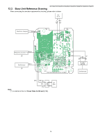
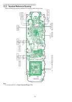
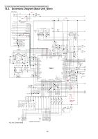
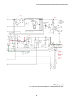
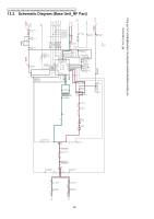
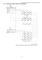
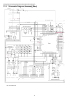
13 Schematic Diagram KX-TG9341T/KX-TG9342T/KX-TG9343S/KX-TG9343T/KX-TG9344T/KX-TGA931S/KX-TGA931T 13.1. For Schematic Diagram 13.1.1. Base Unit (Schematic Diagram (Base Unit_Main)) 13.1.1.1. Acoustic Testing Mode Notes: 1. DC voltage measurements are taken with voltmeter from the negative voltage line. 2. The schematic diagrams may be modified at any time with the development of new technology. 13.1.2. Handset (Schematic Diagram (Handset_Main)) Notes: 1. DC voltage measurements are taken with an oscilloscope or a tester with a ground. 2. The schematic diagrams may be modified at any time with the development of new technology. 13.1.3. Charger Unit (Schematic Diagram (Charger Unit)) Notes: 1. DC voltage measurements are taken with voltmeter from the negative voltage line. 2. The schematic diagrams may be modified at any time with the development of new technology. 79
-
 1
1 -
2
-
3
-
4
-
5
-
6
-
7
-
8
-
9
-
10
-
11
-
12
-
13
-
14
-
15
-
16
-
17
-
18
-
19
-
20
-
21
-
22
-
23
-
24
-
25
-
26
-
27
-
28
-
29
-
30
-
31
-
32
-
33
-
34
-
35
-
36
-
37
-
38
-
39
-
40
-
41
-
42
-
43
-
44
-
45
-
46
-
47
-
48
-
49
-
50
-
51
-
52
-
53
-
54
-
55
-
56
-
57
-
58
-
59
-
60
-
61
-
62
-
63
-
64
-
65
-
66
-
67
-
68
-
69
-
70
-
71
-
72
-
73
-
 74
74 -
 75
75 -
 76
76 -
 77
77 -
 78
78 -
 79
79 -
 80
80 -
 81
81 -
 82
82 -
 83
83 -
 84
84 -
85
-
86
-
87
-
88
-
89
-
90
-
91
-
92
-
93
-
94
-
95
-
96
-
97
-
98
-
99
-
100
-
101
-
102
-
103
-
104
-
105
-
106
-
107
-
108
-
109
-
110
-
111
-
112
-
113
-
114
-
115
 |
 |