Panasonic KX-TG9341T Service Manual - Page 58
Check Table for RF part
 |
UPC - 037988479504
View all Panasonic KX-TG9341T manuals
Add to My Manuals
Save this manual to your list of manuals |
Page 58 highlights
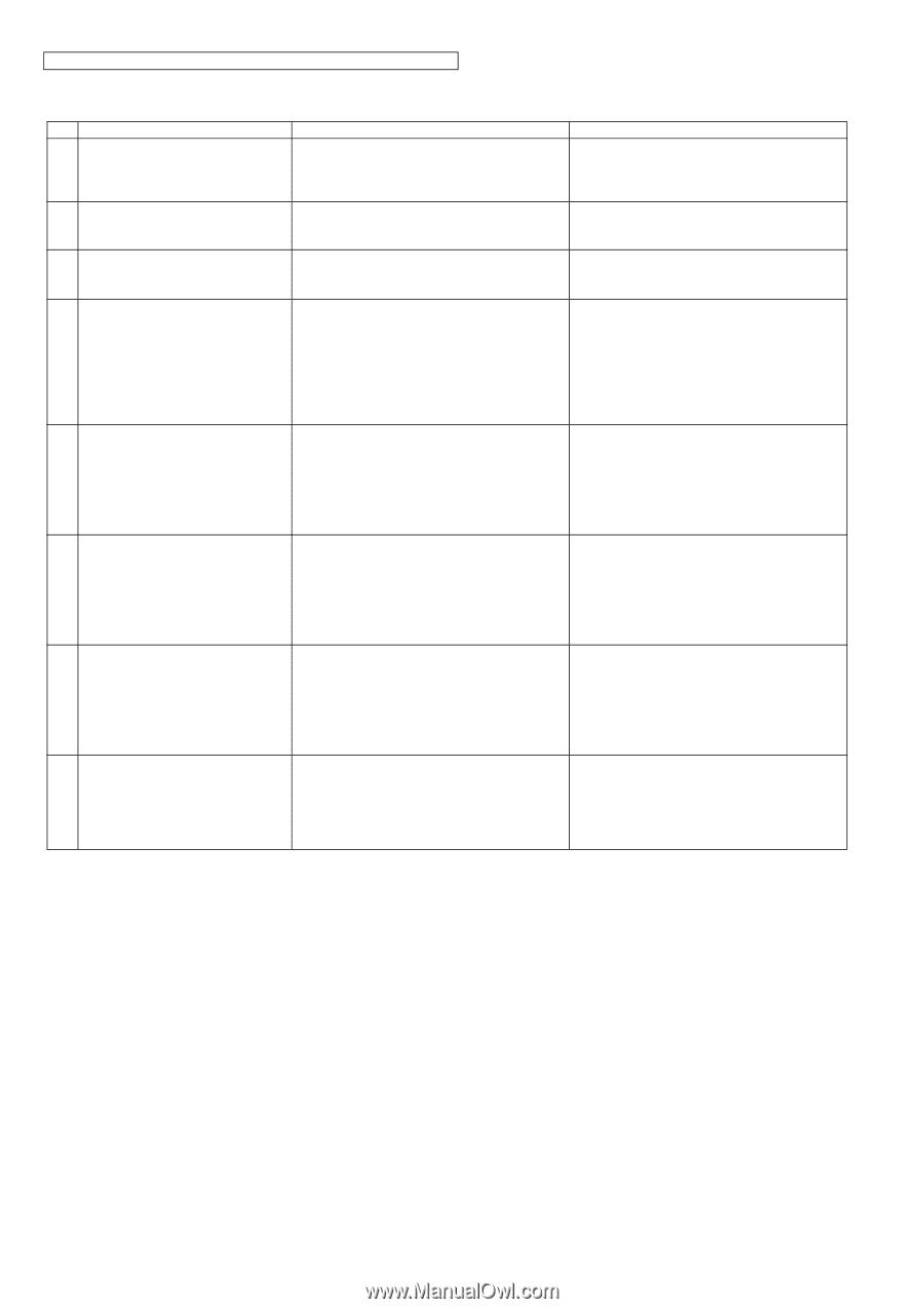
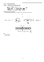
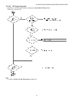
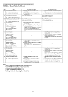
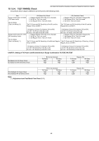
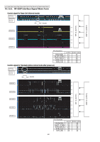
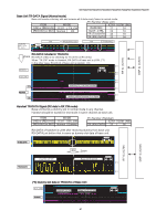
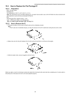
KX-TG9341T/KX-TG9342T/KX-TG9343S/KX-TG9343T/KX-TG9344T/KX-TGA931S/KX-TGA931T 10.1.6.3. Check Table for RF part No. Item 1 Link Confirmation Normal HS, BU Mode [Normal Mode] 2 Control signal confirmation HS, BU Mode: [Normal Mode] (*1) 3 X'tal Frequency confirmation (*8) HS, BU Mode: [Adjustment] (*4) 4-1 TX confirmation Regular HS Mode: [Test RX_CW Mode] (*5) ↑ [AIR] BU (to be checked) Mode: [Normal Mode] 4-2 TX confirmation Regular BU Mode: [Normal Mode] ↑ [AIR] HS (to be checked) Mode: [TEST TX_CW Mode] (*5) 5-1 RX confirmation Regular HS Mode: [Test TX_CW Mode] (*5) ↓ [AIR] BU (to be checked) Mode: [Normal Mode] 5-2 RX confirmation Regular BU Mode: [Normal Mode] ↓ [AIR] HS (to be checked) Mode: [TEST RX_CW Mode] (*5) 6 Range Confirmation Normal HS, BU Mode: [Normal Mode] BU (Base Unit) Check 1. Register Regular HS to BU (to be checked). 2. Press [Talk] key of the Regular HS to establish link. Check DSP interface. (*2) HS (Handset) Check 1. Register HS (to be checked) to Regular BU. 2. Press [Talk] key of the HS to establish link. Check DSP interface. (*3) Check signal at power-on. Check X'tal Frequency. (13.824000 MHz ±100 Hz) Check X'tal Frequency. (13.824000 MHz ±100 Hz) 1. Place Regular HS 15 cm away from a checked BU. 2. Confirm "RXDATA" waveform of Regular HS by Oscilloscope. Please try to vary Regular HS CH from 00 ch to 04 ch to be matched to the BU dummy CH, then the waveform is verified. (*6) - - 1. Place Regular BU 15 cm away from a checked HS. 2. Confirm "RXDATA" waveform of Regular BU by Oscilloscope. (*7) When Regular BU scans TX_CW, RXDATA is LOW. 1. Place Regular HS 15cm away from a checked BU. 2. Confirm "RXDATA" waveform of the BU by Oscilloscope. (*7) - When the BU scans TX_CW, RXDATA is LOW. - 1. Register Regular HS to BU (to be checked). 2. Press [Talk] key of the Regular HS to establish link. 3. Compare the range of the BU (being checked) with that of the Regular BU. 1. Place Regular BU 15 cm away from a checked HS. 2. Confirm "RXDATA" waveform of the HS by Oscilloscope. Please try to vary the HS CH from 00 ch to 04 ch to be matched to Regular BU dummy CH, then the waveform is verified. (*6) 1. Register HS (to be checked) to Regular BU. 2. Press [Talk] key of the HS to establish link. 3. Compare the range of the HS (being checked) with that of the Regular HS. Note: (*1)(*4)(*5) Adjustment and Test Mode Flow Chart (P.41) (*2)(*3) RF-DSP Interface Signal Wave Form (P.60) (*6) Handset Reference Drawing (P.76) (*7) Base Unit Reference Drawing (P.75) (*8) Things to Do after Replacing IC or X'tal (P.74) 58
-
 1
1 -
2
-
3
-
4
-
5
-
6
-
7
-
8
-
9
-
10
-
11
-
12
-
13
-
14
-
15
-
16
-
17
-
18
-
19
-
20
-
21
-
22
-
23
-
24
-
25
-
26
-
27
-
28
-
29
-
30
-
31
-
32
-
33
-
34
-
35
-
36
-
37
-
38
-
39
-
40
-
41
-
42
-
43
-
44
-
45
-
46
-
47
-
48
-
49
-
50
-
51
-
52
-
 53
53 -
 54
54 -
 55
55 -
 56
56 -
 57
57 -
 58
58 -
 59
59 -
 60
60 -
 61
61 -
 62
62 -
 63
63 -
64
-
65
-
66
-
67
-
68
-
69
-
70
-
71
-
72
-
73
-
74
-
75
-
76
-
77
-
78
-
79
-
80
-
81
-
82
-
83
-
84
-
85
-
86
-
87
-
88
-
89
-
90
-
91
-
92
-
93
-
94
-
95
-
96
-
97
-
98
-
99
-
100
-
101
-
102
-
103
-
104
-
105
-
106
-
107
-
108
-
109
-
110
-
111
-
112
-
113
-
114
-
115
 |
 |