Panasonic KX-TG9341T Service Manual - Page 65
How to Replace the LLP Leadless Leadframe Package IC
 |
UPC - 037988479504
View all Panasonic KX-TG9341T manuals
Add to My Manuals
Save this manual to your list of manuals |
Page 65 highlights
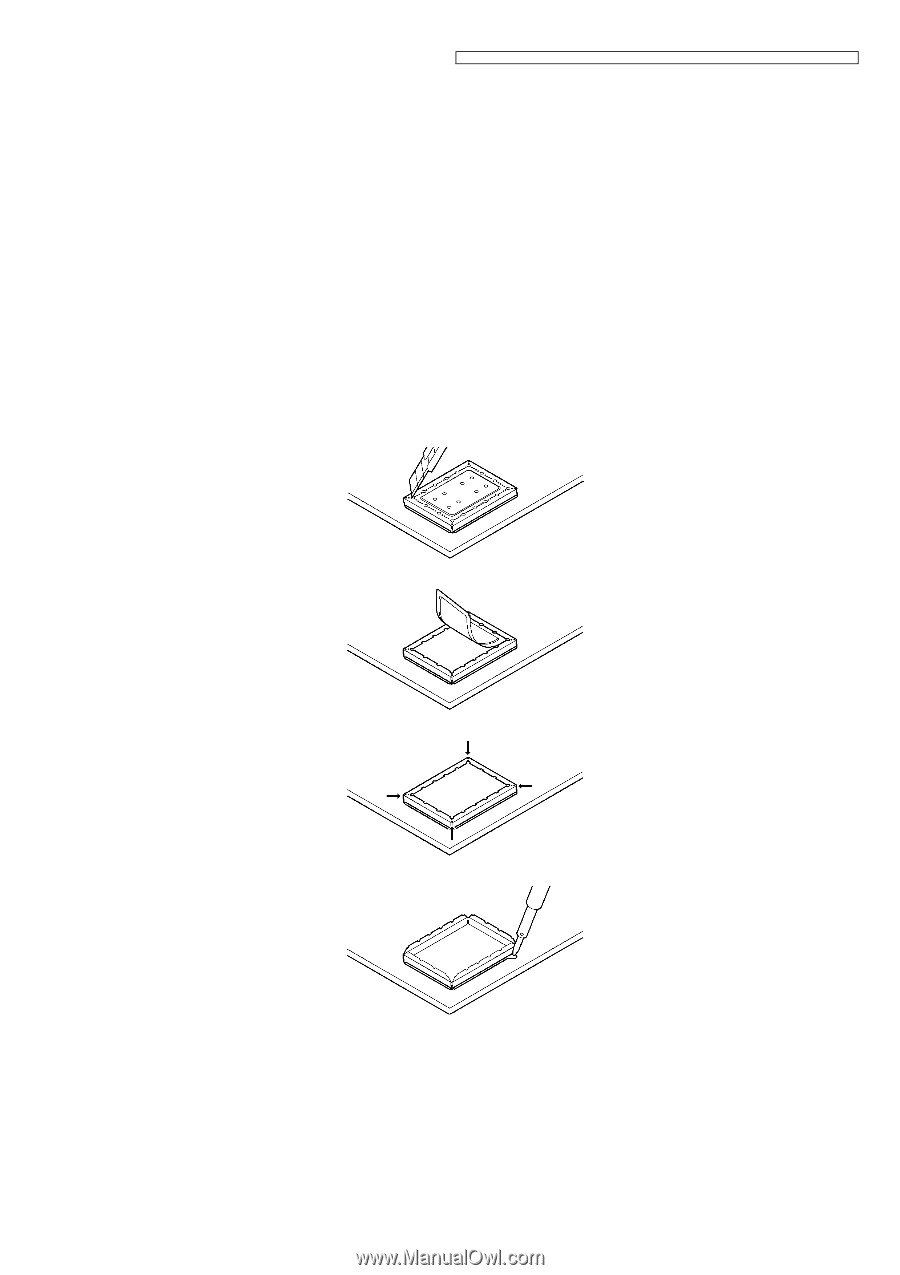
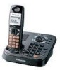
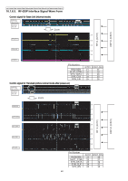
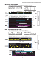
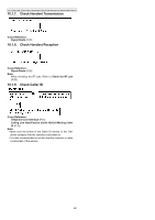
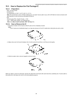
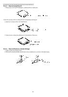
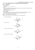
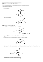
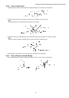
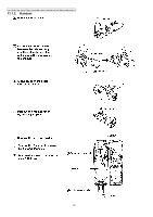
KX-TG9341T/KX-TG9342T/KX-TG9343S/KX-TG9343T/KX-TG9344T/KX-TGA931S/KX-TGA931T 10.3. How to Replace the LLP (Leadless Leadframe Package) IC 10.3.1. Preparation • PbF (: Pb free) Solder • Soldering Iron Tip Temperature of 700 °F ± 20 °F (370 °C ± 10 °C) Note: We recommend a 30 to 40 Watt soldering iron. An expert may be able to use a 60 to 80 Watt iron where someone with less experience could overheat and damage the PCB foil. • Hot Air Desoldering Tool Temperature: 608 °F ± 68 °F (320 °C ± 20 °C) 10.3.2. Caution • To replace the IC efficiently, choose the right sized nozzle of the hot air desoldering tool that matches the IC package. • Be careful about the temperature of the hot air desoldering tool not to damage the PCB and/or IC. 10.3.3. How to Remove the Shield Case Note: If you don't have special tools (ex. Hot air disordering tool), conduct the following operations. 1. Cut the case along perforation. 2. Remove the cut part. 3. Cut the four corners along perforation. 4. Remove the reminds by melting solder. 65
-
 1
1 -
2
-
3
-
4
-
5
-
6
-
7
-
8
-
9
-
10
-
11
-
12
-
13
-
14
-
15
-
16
-
17
-
18
-
19
-
20
-
21
-
22
-
23
-
24
-
25
-
26
-
27
-
28
-
29
-
30
-
31
-
32
-
33
-
34
-
35
-
36
-
37
-
38
-
39
-
40
-
41
-
42
-
43
-
44
-
45
-
46
-
47
-
48
-
49
-
50
-
51
-
52
-
53
-
54
-
55
-
56
-
57
-
58
-
59
-
 60
60 -
 61
61 -
 62
62 -
 63
63 -
 64
64 -
 65
65 -
 66
66 -
 67
67 -
 68
68 -
 69
69 -
 70
70 -
71
-
72
-
73
-
74
-
75
-
76
-
77
-
78
-
79
-
80
-
81
-
82
-
83
-
84
-
85
-
86
-
87
-
88
-
89
-
90
-
91
-
92
-
93
-
94
-
95
-
96
-
97
-
98
-
99
-
100
-
101
-
102
-
103
-
104
-
105
-
106
-
107
-
108
-
109
-
110
-
111
-
112
-
113
-
114
-
115
 |
 |