Panasonic WJ-GXE500 Installation Guide - Page 21
OFF: Open or 4.5 V - 5.5 V DC
 |
View all Panasonic WJ-GXE500 manuals
Add to My Manuals
Save this manual to your list of manuals |
Page 21 highlights
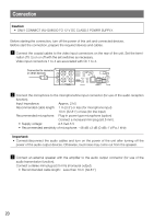
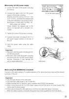
v Connect an external device to the EXT I/O terminals. Strip range When connecting an external device, remove 9 mm - 10 mm {11/32" - 13/32"} of the outer jacket of the cable and twist the cable core to prevent the short circuit first. Specification of cable (wire): 22 AWG - 28 AWG 9 mm - 10 mm {11/32" - 13/32"} Single core, twisted * Check whether the stripped part of the wire is not exposed and is securely connected. Terminal 4: GND Terminal 3: Alarm input/Alarm output/ AUX output 4 3 2 1 Terminal 1: Alarm input Terminal 2: Alarm input/Alarm output Important: • Do not connect 2 wires or more directly to a terminal. When it is necessary to connect 2 or more wires, use a splitter. • Connect an external device with verifying that the ratings are within the specifications above. • When using the EXT I/O terminals as the output terminals, ensure they do not cause signal col- lision with external signals. • Alarm output AUX output Output specification: Open collector output (maximum applied voltage: 20 V DC) Open: 4.5 V - 5.5 V DC by internal pull-up Close: Output voltage 1 V DC or less (50 mA or less) • Alarm input Input specification: No-voltage make contact input (4.5 V - 5.5 V DC, internally pulled up) OFF: Open or 4.5 V - 5.5 V DC ON: Make contact with GND (required drive current: 1 mA or more) 21
-
 1
1 -
2
-
3
-
4
-
5
-
6
-
7
-
8
-
9
-
10
-
11
-
12
-
13
-
14
-
15
-
 16
16 -
 17
17 -
 18
18 -
 19
19 -
 20
20 -
 21
21 -
 22
22 -
 23
23 -
 24
24 -
 25
25 -
 26
26 -
27
-
28
-
29
-
30
-
31
-
32
 |
 |
