Panasonic WVCP284 Color Cctv Camera - Multi Language - Page 11
Installations And Connections
 |
UPC - 791871505069
View all Panasonic WVCP284 manuals
Add to My Manuals
Save this manual to your list of manuals |
Page 11 highlights
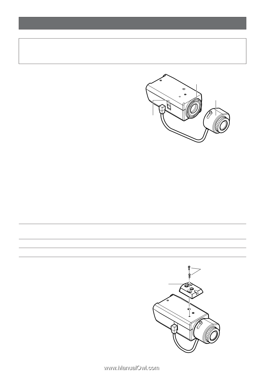
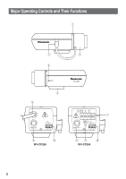
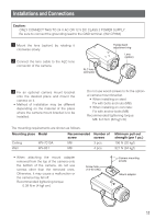
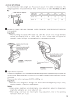
Installations and Connections Caution: ONLY CONNECT THIS TO 24 V AC OR 12 V DC CLASS 2 POWER SUPPLY. Be sure to connect the grounding lead to the GND terminal. (WV-CP284) z Mount the lens (option) by rotating it clockwise slowly. x Connect the lens cable to the ALC lens connector of the camera. ALC lens connector Flange-back adjustment ring Lens (option) c Fix an optional camera mount bracket onto the desired place and mount the camera on it. • Method of installation may be different depending on the material of the place where the camera mount bracket is to be installed. Do not use wood screws to fix the optional camera mount bracket. • When installing on steel: Fix with bolts and nuts (M8). • When installing on concrete: Fix with anchor bolts (M8) Recommended tightening torque: M8: 6.2 N·m {62 kgf·cm} The mounting requirements are shown as follows. Mounting place Model Ceiling Wall WV-7010A WV-831 Recommended screw M8 M8 Number of screws 3 pcs. 4 pcs. Minimum pull-out strength (per 1 pc.) 196 N {20 kgf} 921 N {94 kgf} • When attaching the mount adapter removed from the top of the camera onto the bottom of the camera, do not use screws other than the removed ones. Otherwise, it may cause a malfunction or the camera may fall off. Recommended tightening torque: 0.39 N·m {4 kgf·cm} Screw hole (1/4-20 UNC) Camera mounting screws Mount adapter 11
-
 1
1 -
2
-
3
-
4
-
5
-
 6
6 -
 7
7 -
 8
8 -
 9
9 -
 10
10 -
 11
11 -
 12
12 -
 13
13 -
 14
14 -
 15
15 -
 16
16 -
17
-
18
-
19
-
20
-
21
-
22
-
23
-
24
-
25
-
26
-
27
-
28
-
29
-
30
-
31
-
32
 |
 |