Panasonic WVCP284 Color Cctv Camera - Multi Language - Page 9
V IN/DC 12V IN] WV-CP284 only, V AC/12 V DC input terminal [AC - wv cp284 camera
 |
UPC - 791871505069
View all Panasonic WVCP284 manuals
Add to My Manuals
Save this manual to your list of manuals |
Page 9 highlights
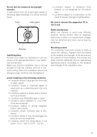
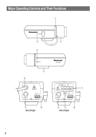
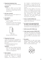
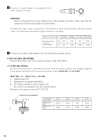
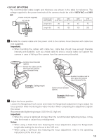
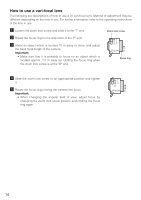
q Flange-back adjustment ring This ring adjusts the back-focal distance or picture focus. Important: • When an object is out of focus because it is too close to the camera, focus on a darker object with the aperture open. w ALC lens connector Supplies power and control signals to an auto iris lens (option). e Lens (option) Important: • The lens mount should be a CSmount (1"-32UN). • The protrusion at the rear of the lens should be as shown in the diagram to prevent the camera's damage. CS-mount: Less than 8 mm {5/16"} r Flange-back lock screw Loosen this screw with a screwdriver to adjust the flange-back adjustment ring. When completing the adjustment, tighten this screw. Recommended tightening torque: 0.05 N·m {0.5 kgf·cm} Important: • When the screw is tightened stronger than the recommended tightening torque, it may strip the thread or cause focus misalignment. t Mount adapter The camera mounting screw hole is for mounting the camera onto a mounting bracket. The camera is originally designed to be mounted from the bot- tom, however, a top-mounting type is also available. To mount from the top, remove the mount adapter from the bottom of the camera by removing two fixing screws. Attach the mount adapter to the top as shown in the diagram, then mount the camera on the mounting bracket. Make sure that two original screws are used when mounting the mount adapter; longer type screws may damage inner components, too shorter type screws may cause the camera drop. y Power cord (WV-CP280 only) Connect this power cord to an electrical outlet of 120 V AC 60 Hz. u 24 V AC/12 V DC input terminal [AC 24V IN/DC 12V IN] (WV-CP284 only) This terminal is for connecting the 24 V AC 60 Hz/12 V DC power supply cord. i GND terminal (WV-CP284 only) o Video output connector [VIDEO OUT] Composite video signals are transmitted. If this unit is connected to the multiplex unit, the multiplexed VD2 that is prioritized over INT/LL is automatically selected. !0 Dip switch Selects ON/OFF for light control mode, backlight compensation, Adaptive Black Stretch, simple day/night mode, and INT/LL for synchronization mode. B.S. D/N BLC ON ALC ON ON INT OFF OFF LL OFF ELC 9
-
 1
1 -
2
-
3
-
 4
4 -
 5
5 -
 6
6 -
 7
7 -
 8
8 -
 9
9 -
 10
10 -
 11
11 -
 12
12 -
 13
13 -
 14
14 -
15
-
16
-
17
-
18
-
19
-
20
-
21
-
22
-
23
-
24
-
25
-
26
-
27
-
28
-
29
-
30
-
31
-
32
 |
 |
