Panasonic WVCP464 WVCP460 User Guide - Page 8
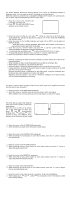
VBS Gen-lock Mode EXT VBS, 2. VS Gen-lock Mode EXT VS
 |
View all Panasonic WVCP464 manuals
Add to My Manuals
Save this manual to your list of manuals |
Page 8 highlights
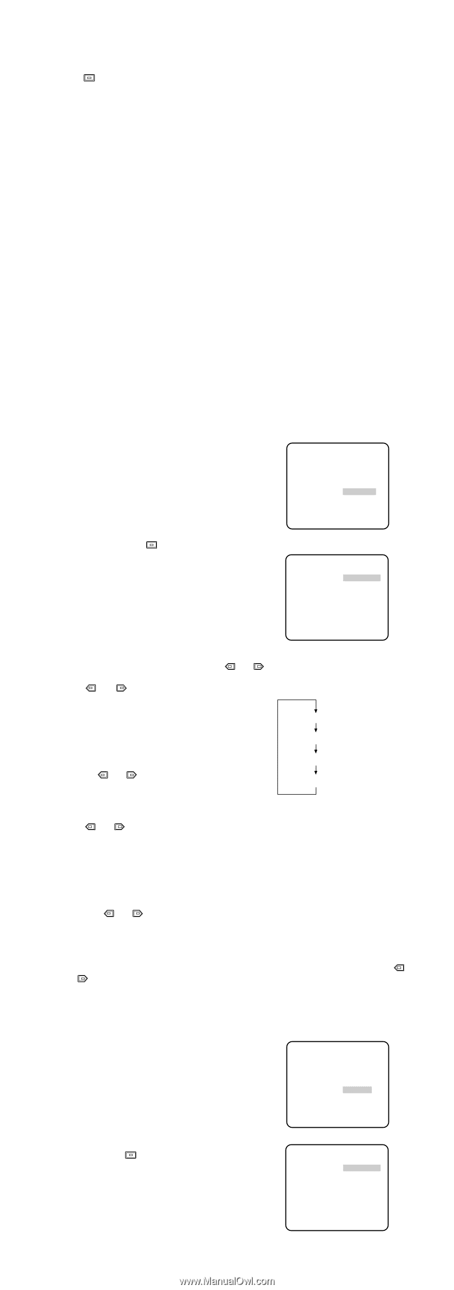
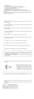
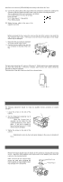
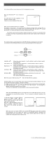
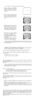
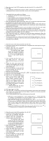
1. Move the cursor to the SYNC parameter and select line-lock (LL) or internal (INT). 2. Press . If LL is selected, the SYNC menu appears. (If INT is selected, the synchronization mode is automatically set to internal sync pulse, and the menu is not displayed.) Important Notice: 1. The priority for the sync modes is as follows: 1. Multiplexed Vertical Drive (VD2) (Highest priority) 2. Line-lock (LL) 3. Color Composite Video or Blackburst Signal (VBS) 4. B/W Composite Video or Composite Sync Signal (VS) 5. Internal Sync (INT) (Lowest priority) 2. When the internal sync mode is to be used, select INT. No gen-lock input signal should be supplied to the Gen-lock Input Connector on the rear panel. 3. Whenever the multiplexed vertical drive pulse (VD2) is supplied to the camera from an external equipment such as a Matrix Switcher, the camera sync mode is automatically switched to the VD2 mode. 4. When the VBS or VS gen-lock mode is to be used select INT from this menu and supply the gen-lock input signal to the Gen-lock Input Connector on the rear panel. 5. The VBS gen-lock mode has a submenu for horizontal and subcarrier phase adjustments. When the cable length of the video output or the gen-lock input is changed, the horizontal and subcarrier phase must be re-adjusted. 6. The VS gen-lock mode has a submenu for horizontal phase adjustments. When the cable length of the video output or the gen-lock input is changed, the horizontal phase must be re-adjusted. 7. The line-lock mode has a submenu for line-lock vertical phase adjustment. If the camera installation is relocated, check the vertical phase adjustment again since the AC line phase may be different. 6-1. VBS Gen-lock Mode (EXT (VBS)) 1. Move the cursor to the SYNC parameter and select INT. 2. Connect the coaxial cable for the blackburst or composite color video signal to the gen- lock input connector. 3. Confirm that the INT parameter changed to EXT (VBS) on the menu. Caution: The gen-lock input signal should meet EIA RS-170A specifications and should not contain jitter, such as a VCR playback signal, as it could disturb synchronization. ** CAM SET UP ** ↵↵ CAMERA ID OFF ALC/ELC ALC SHUTTER OFF AGC ON SENS UP OFF SYNC EXT(VBS) ↵ WHITE BAL ATW MOTION DET OFF LENS DRIVE DC ↵ END SET UP ENABLE 4. After confirming that the cursor is on EXT (VBS), press . The phase adjustment menu appears on the monitor. 5. Supply the video output signal of the camera to be adjusted and the reference gen-lock input signal to a dualtrace oscilloscope. 6. Set the oscilloscope to the horizontal rate and expand the horizontal sync portion on the oscilloscope. 7. Move the cursor to H PHASE. 8. Adjust the horizontal phase by pressing 9. Move the cursor to SC COARSE. 10. Press or to match the chroma phase of the camera's video signal, when observed at the output of the special effects generator (SEG) or Switcher, as closely as possible to the color of the original scene. (SC COARSE adjustment can be incremented in steps of 90 degrees (4 steps) by pressing or .) Note: After the fourth step, the adjust- ment returns to the first step. ** SYNC ** H PHASE SC COARSE ........I - + 1(1--4) SC FINE ....I.... - + RET END or . The adjustable range is 0-2.0 µs. 1 (1 - - 4): 0 degrees 2 (1 - - 4): 90 degrees 3 (1 - - 4): 180 degrees 4 (1 - - 4): 270 degrees 11. Move the cursor to SC FINE. 12. Press or to match the color (hue) of the camera's video signal, when observed at the output of the special effects generator (SEG) or Switcher, as closely as possible to the color of the original scene. The SC FINE adjustment has a range of 90 degrees of color shift. Notes: • When the "I" cursor reaches the "+" end, it jumps back to "-" . At the same time, SC COARSE is incremented by one step to enable a continuous adjustment. The reverse takes place when the "I" cursor reaches the "-" end. • When or is kept pressed for a second or more, the "I" cursor moves faster. • For more accurate adjustment, supply both the original camera video output signal and the effect output video signal (program output video signal) of the special effects generator (SEG) to a vectorscope and compare the chroma phase of both signals. • To reset SC COARSE and SC FINE to the values preset at the factory, press or simultaneously. SC COARSE is reset to the factory setting. ↵ 6-2. VS Gen-lock Mode (EXT (VS)) 1. Move the cursor to the SYNC parameter and select INT. 2. Connect the coaxial cable for the com- posite sync or composite B/W video signal to the gen-lock input connector. 3. Confirm that the parameter INT changed to EXT (VS) on the menu. Caution: The gen-lock input signal should meet EIA RS-170 specifications and should not contain jitter, ** CAM SET UP ** ↵↵ CAMERA ID OFF ALC/ELC ALC SHUTTER OFF AGC ON SENS UP OFF SYNC EXT(VS) ↵ WHITE BAL ATW MOTION DET OFF LENS DRIVE DC such as a VCR playback signal, as END SET UP ENABLE it could disturb synchronization. 4. After confirming that the cursor is on EXT (VS), press . The phase adjust- ** SYNC ** ment menu appears on the monitor. 5. Supply the video output signal of the H PHASE ........I - + camera to be adjusted and the refer- ence gen-lock input signal to a dual- trace oscilloscope. 6. Set the oscilloscope to the horizontal RET END rate and expand the horizontal sync portion on the oscilloscope. 7. Move the cursor to H PHASE.
-
 1
1 -
2
-
 3
3 -
 4
4 -
 5
5 -
 6
6 -
 7
7 -
 8
8 -
 9
9 -
 10
10 -
 11
11
 |
 |