Panasonic WVCP464 WVCP460 User Guide - Page 9
White Balance Setting WHITE BAL
 |
View all Panasonic WVCP464 manuals
Add to My Manuals
Save this manual to your list of manuals |
Page 9 highlights
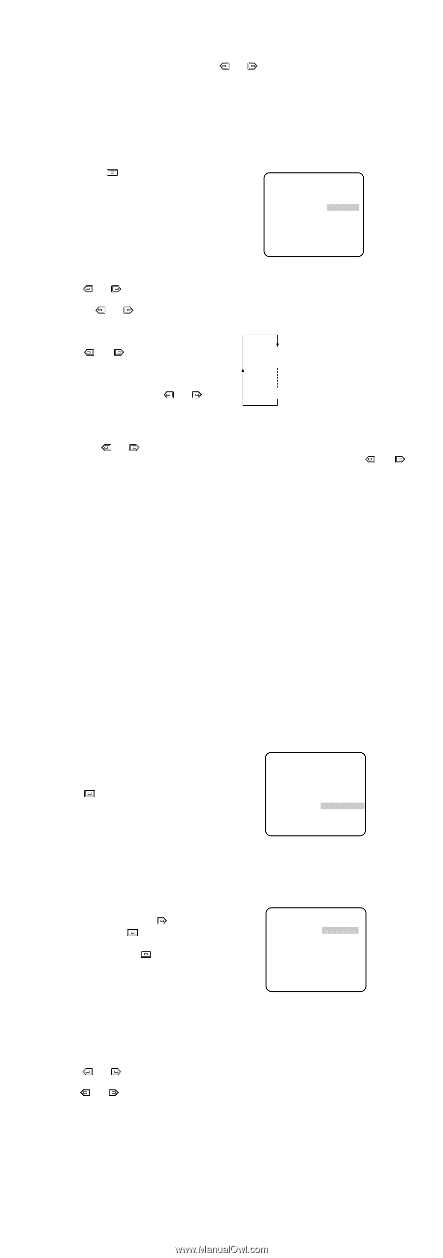
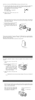
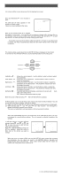
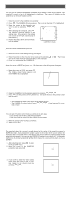
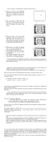
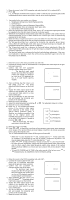
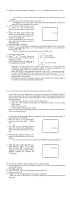
8. Adjust the horizontal phase by pressing or . The adjustable range is 0-2.0 µs. 6-3. Line-lock Sync Mode (LL) Note: The line-lock (LL) sync mode is not available when the camera operates on DC power. 1. Move the cursor to the SYNC parameter and select LL. Note: The settings in this menu can be made only when the multiplexed vertical drive signal (VD2) is not supplied to the camera. 2. After confirming that the cursor is on LL, press . The vertical phase adjustment menu appears on the moni- ** SYNC ** tor. V PHASE 3. Supply the video output signal of the COARSE 1(1--16) camera to be adjusted and the reference camera video output signal to a FINE I........ - + dual-trace oscilloscope. 4. Set the oscilloscope to the vertical rate RET END and expand the vertical sync portion on the oscilloscope. 5. Move the cursor to COARSE. 6. Press or to match the vertical phase for both video output signals as closely as possible. (COARSE adjustment can be incremented in 16 steps by 22.5 degrees by pressing or .) Note: After the sixteenth step, the adjustment returns to the first step. 7. Move the cursor to FINE. 8. Press or to match the vertical phase for both video output signals as 1 (1 - - 16): 0 degrees 2 (1 - - 16): 22.5 degrees closely as possible. (FINE adjustment can be made up to 22.5 degrees by pressing or .) 16 (1 - - 16): 337.5 degrees Notes: • When the "I" cursor reaches the "+" end, it jumps back to "-". At the same time, COARSE is incremented by one step to enable a continuous adjustment. The reverse takes place when the "I" cursor reaches the "-" end. • When or is kept pressed for a second or more, the "I" cursor moves faster. • To reset COARSE and FINE to the values preset at the factory, press or simultaneously. COARSE and FINE adjustments are preset at the factory to zero- crossing of the AC line phase. • If the AC line contains noise (spike noise, etc.), the stability of the vertical phase of the camera video output signal may be disturbed. 7. White Balance Setting (WHITE BAL) 7-1. Auto-Tracing White Balance Mode (ATW) You can select one of two modes for white balance adjustment as follows: • ATW (Auto Tracing White Balance) In this mode, the color temperature is monitored continuously and thereby white balance is set automatically. The color temperature range for the proper white balance is approximately 2 600 - 6 000K. Proper white balance may not be obtained under the following conditions: 1. The color temperature is out of the 2 600 - 6 000K range. 2. When the scene contains mostly high color temperature objects, such as a blue sky or sunset. 3. When the scene is dim. In these cases, select the AWC mode. Move the cursor to the WHITE BAL parameter and select ATW. The white balance of the camera is automatically set. • Automatic White Balance Control Mode (AWC) In this mode, accurate white balance is obtained within a color temperature range of approximately 2 300-10 000K. 1. Move the cursor to the WHITE BAL parameter and select AWC → PUSH SW. 2. Press to start the white balance setup. The PUSH SW is highlighted to indicate that the white balance is being set. ** CAM SET UP ** CAMERA ID OFF ALC/ELC ALC SHUTTER OFF AGC ON SENS UP OFF SYNC INT WHITE BAL AWC→PUSH SW MOTION DET OFF LENS DRIVE DC END SET UP ENABLE 3. When the white balance setting is completed, the PUSH SW returns to normal display. Note: In case that the white balance is not set, the PUSH SW Is being highlighted. ↵ ↵↵ 4. When you want to adjust the white bal- ance manually, press to select AWC and press . The AWC menu appears on the monitor. (When ATW is selected, pressing displays the ATW menu.) ** AWC ** R ....I.... - + B ....I.... - + MASK SET RET END Fine Adjustment for AWC (ATW) Manually You can add the detailed setting for white balance setting manually. 1. To set MASK SET, proceed as described in steps 2 to 4 of "ALC mode with SUPER-D2 OFF and ELC mode". 2. Move the cursor to R. 3. Press or to obtain the optimum amount of red gain. 4. Move the cursor to B. 5. Press or to obtain the optimum amount of blue gain. Note: When you need to set MASK SET, re-adjust to obtain the optimum amount of red and blue gain.
-
 1
1 -
2
-
3
-
 4
4 -
 5
5 -
 6
6 -
 7
7 -
 8
8 -
 9
9 -
 10
10 -
 11
11
 |
 |