Panasonic WVCW384 WVCW384 User Guide - Page 10
Installations/Connections, Preparations, Camera installation
 |
UPC - 791871505830
View all Panasonic WVCW384 manuals
Add to My Manuals
Save this manual to your list of manuals |
Page 10 highlights
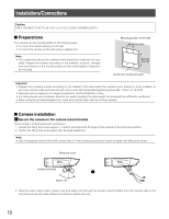
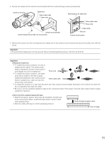
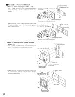
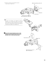
Installations/Connections Caution: ONLY CONNECT THIS TO 24 V AC or 12 V DC CLASS 2 POWER SUPPLY. Preparations The camera can be mounted either of the following ways. • To mount the camera directly on the wall • To mount the camera on the wall using a adapter box Note: • The screws that secure the camera mount bracket on a wall are not sup- plied. Prepare the screws according to the material, structure, strength and other factors of the mounting area and the total weight of objects to be mounted. [Mounting position on the wall] 46 mm {1-13/16"} 83.5 mm {3-5/16"} Junction box (locally procured) Important: • Prepare the mounting screws according to the material of the area where the camera mount bracket is to be installed. In this case, wood screws and nails should not be used. Recommended tightening torque M4: 1.6 N·m {1.18 lbf·ft} • Required pull-out capacity of a single screw/bolt is 196 N {44.06 lbf} or more. • If a ceiling board such as plaster board is too weak to support the total weight, the area shall be sufficiently reinforced. • When using the provided adapter box, make sure that the drain slits do not face upward. Camera installation z Secure the camera to the camera mount bracket The tilt angle is locked downward at shipment. 1. Loosen the tilting lock screw approx. 1 rotation and adjust the tilt angle of the camera to the horizontal position. 2. Tighten the tilting lock screw again after tilt angle adjustment. Note: • Use a hexagonal wrench with width across flats of 4 mm (locally procured) to loosen or tighten the tilting lock screw. Tilting lock screw Camera main body Approx. 90° 3. Pass the video output cable, power cord and safety wire through the camera mount bracket from the camera side to the wall side and use the cable clamp to bundle the cables and wire. 10
-
 1
1 -
2
-
3
-
4
-
 5
5 -
 6
6 -
 7
7 -
 8
8 -
 9
9 -
 10
10 -
 11
11 -
 12
12 -
 13
13 -
 14
14 -
 15
15 -
16
-
17
-
18
-
19
-
20
-
21
-
22
-
23
-
24
-
25
-
26
-
27
-
28
-
29
-
30
-
31
-
32
-
33
-
34
-
35
-
36
-
37
-
38
-
39
-
40
-
41
-
42
-
43
-
44
-
45
-
46
-
47
-
48
-
49
-
50
-
51
-
52
-
53
-
54
-
55
-
56
-
57
-
58
-
59
-
60
-
61
-
62
-
63
-
64
-
65
-
66
-
67
-
68
-
69
-
70
-
71
-
72
-
73
-
74
 |
 |
