Panasonic WVSF332 WVSF332 User Guide - Page 25
When using 12 V DC power supply, Open or 4 V - 5 V DC
 |
View all Panasonic WVSF332 manuals
Add to My Manuals
Save this manual to your list of manuals |
Page 25 highlights
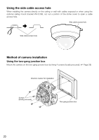
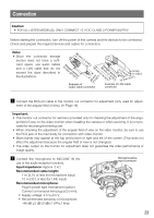
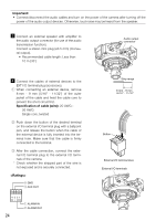
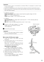
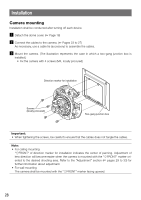
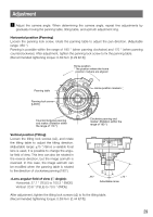
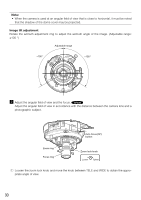
Important: • Do not connect 2 wires or more directly to a terminal. When it is necessary to connect 2 wires or more, use a splitter. • Connect an external device with verifying that the ratings are within the specifications above. • When using the EXT I/O terminals as the output terminals, ensure they do not cause signal col- lision with external signals. • ALARM OUT, AUX OUT Output specification: Open collector output (maximum applied voltage: 20 V DC) Open: 4 V - 5 V DC by internal pull-up Close: Output voltage 1 V DC or less (50 mA or less) • ALARM IN Input specification: No-voltage make contact input (4 V - 5 V DC, internally pulled up) OFF: Open or 4 V - 5 V DC ON: Make contact with GND (required drive current: 1 mA or more) b Connect a LAN cable (category 5 or better, straight, STP*) to the network connector. * PAL models only n Connect the power supply. Important: • The 12 V DC power supply shall be insulated from the commercial AC power. MONITO OU RT Network connector FTROOPNT 4 EXT 3 I/O 21 AUODUITO MLICIN/ E IN 101B0A0SBEA-STE/-IX IN F When using 12 V DC power supply q Loosen the screw of the power cord plug (accessory). w Connect the cable of the 12 V DC power sup- ply* to the power cord plug. Strip 3 mm - 7 mm {1/8" - 9/32"} from the end of the wire, and twist the stripped part of the wire sufficiently to avoid short circuit. Specification of cable (wire): 16 AWG - 24 AWG, Single core, twisted • Check whether the stripped part of the wire is not exposed and is securely connected. e Tighten the screw of the power cord plug. r Connect the power cord plug to the 12 V DC power supply terminal. * FOR UL LISTED MODEL(S), ONLY CONNECT 12 V DC CLASS 2 POWER SUPPLY. (GND) (12 V DC) 12 V DC power cord plug (accessory) 25
-
 1
1 -
2
-
3
-
4
-
5
-
6
-
7
-
8
-
9
-
10
-
11
-
12
-
13
-
14
-
15
-
16
-
17
-
18
-
19
-
 20
20 -
 21
21 -
 22
22 -
 23
23 -
 24
24 -
 25
25 -
 26
26 -
 27
27 -
 28
28 -
 29
29 -
 30
30 -
31
-
32
-
33
-
34
-
35
-
36
-
37
-
38
-
39
-
40
-
41
-
42
-
43
-
44
 |
 |
