Philips DVD622 User manual - Page 11
Using Component Video jacks, Y Pb Pr, Using an accessory RF modulator - player
 |
UPC - 037849959480
View all Philips DVD622 manuals
Add to My Manuals
Save this manual to your list of manuals |
Page 11 highlights
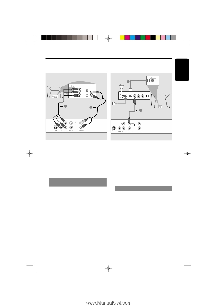
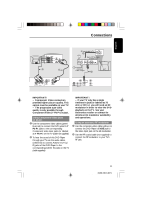
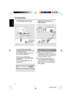
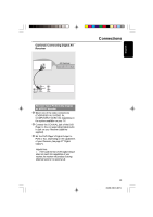
English COMPONENT VIDEO IN S-VIDEO IN V (Pr/Cr) AUDIO OUT VIDEO IN U (Pb/Cb) Y 1 COMPONENT VIDEO IN V (Pr/Cr) S-VIDEO IN U (Pb/Cb) VIDEO IN Y AUDIO IN 2 Connections RF coaxial cable to TV 2 Back of RF Modulator (example only) INT IN TO TV VIDEO IN AUDIO IN R L CH3 CH4 Antenna or Cable TV signal 1 IMPORTANT! - Component Video connection provides higher picture quality. This option must be available on your TV. - The progressive scan video quality is only possible through Component Video (Y Pb Pr) output. Using Component Video jacks (Y Pb Pr) 1 Use the component video cables (green/ blue/red) to connect the DVD system's Y Pb Pr jacks to the corresponding Component video input jacks (or labeled as Y Pb Pr) on the TV (cable not supplied). 2 To hear the sound of this DVD Player through your TV, use the audio cables (white/red) to connect AUDIO OUT (L/ R) jacks of the DVD Player to the corresponding AUDIO IN jacks on the TV (cable supplied). IMPORTANT! - If your TV only has a single Antenna In jack (or labeled as 75 ohm or RF In,) you will need an RF modulator in order to view the DVD playback on the TV. See your electronics retailer or contact for details on RF modulator availability and operations. Using an accessory RF modulator 1 Use the composite video cable (yellow) to connect the DVD Player's CVBS jack to the video input jack on the RF modulator. 2 Use the RF coaxial cable (not supplied) to connect the RF modulator to your TV's RF jack. 01-36 DVD622_372 11 11 18/01/2005, 2:203A1M39 246 14871
-
 1
1 -
2
-
3
-
4
-
5
-
 6
6 -
 7
7 -
 8
8 -
 9
9 -
 10
10 -
 11
11 -
 12
12 -
 13
13 -
 14
14 -
 15
15 -
 16
16 -
17
-
18
-
19
-
20
-
21
-
22
-
23
-
24
-
25
-
26
-
27
-
28
-
29
-
30
-
31
-
32
-
33
-
34
-
35
-
36
 |
 |